Home Automation – Making a dumb switch for smart lights.
by firestorm_v1 on Feb.23, 2016, under Embedded devices, Hardware, How-To's, IoT
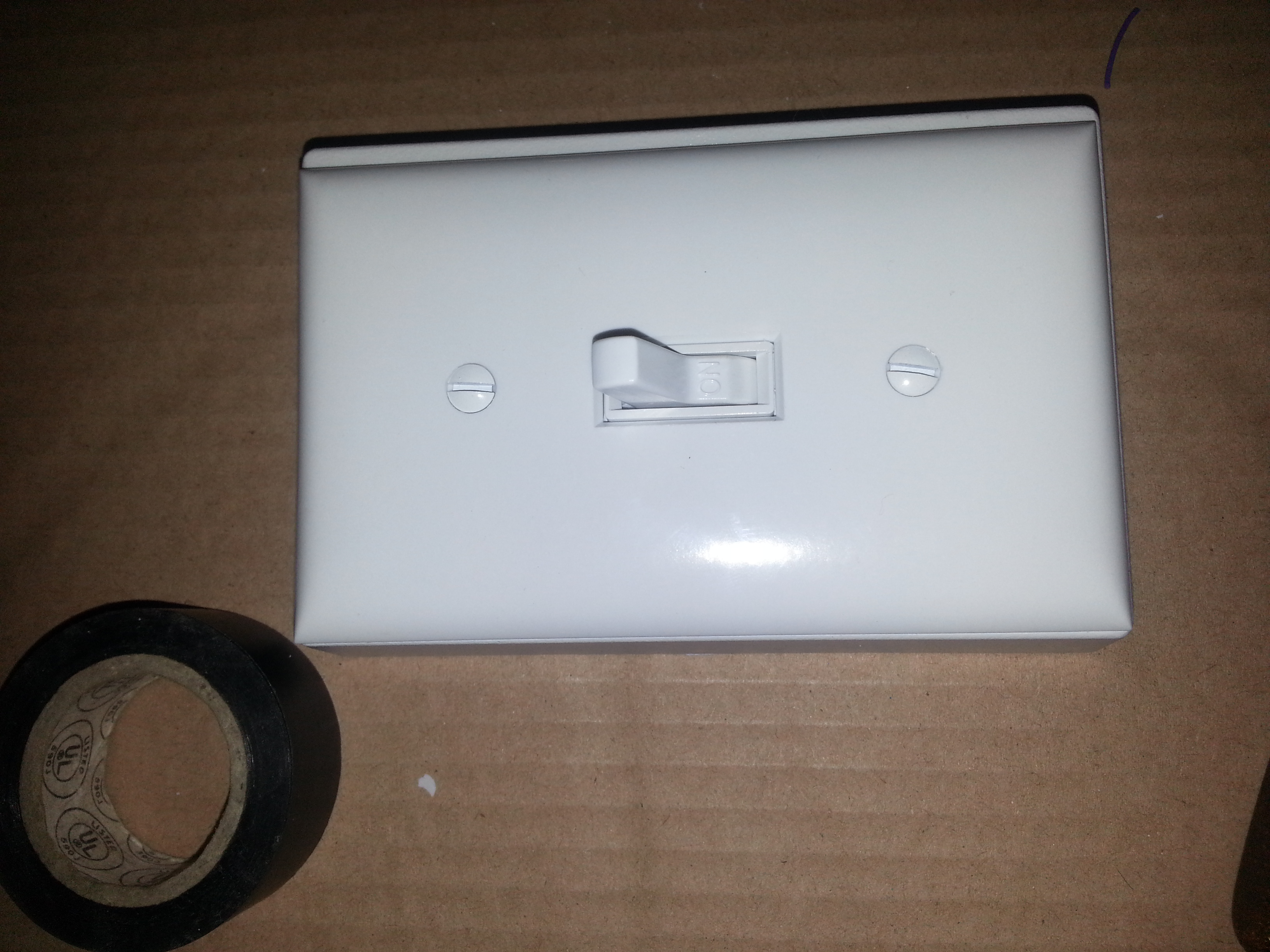
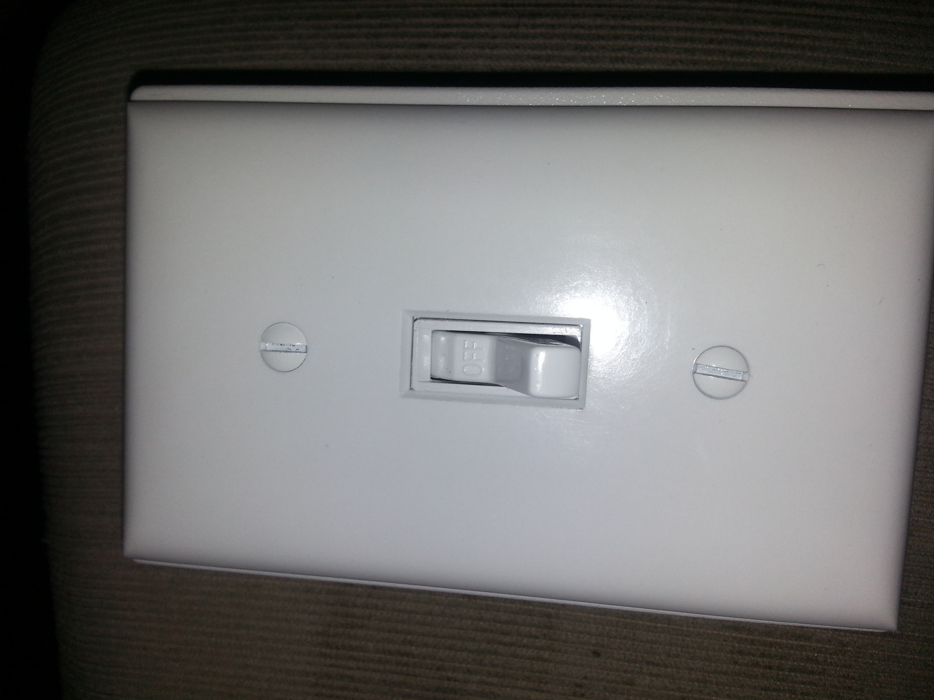 It might not look like much, but the switch used as this feature image has more to offer than one would think judging by appearances. In this article, we will be converting a “stupid” switch into a “smart” switch for the purposes of controlling a connected GE Light Bulb over Z-wave and discuss why you’d want to look for a stupid switch for smart devices in the first place.
The Robot Uprising isn’t as violent as one would think…
I’ll admit that up until this last December-gift-giving-holiday, I wasn’t sure about this whole “Smart Home” nonsense. Why in the heck would I want to control my lights with my phone, and why would I want to cave in to the Internet of Things craze that has been blasted all over the media and news outlets? I had concerns, some of which are still valid, but some of which were put to ease. When my wife wanted an Alexa voice-activated assistant device, I was intrigued when I saw that it had several options for home automation. Later that month, a friend of mine had completely switched away from one Home Automation system to another and was selling his gear off at a very nice price so I took the bait and decided to try it out. I will be writing an article soon about my experiences with the Internet of Things, Home Automation, and the fun of trying to serial debug a finicky Wink Hub, but I’m drifting off topic here. Suffice it to say that I have been very happy with my setup, with one glaring omission.
In my Home Automation gear, I have several GE Link lightbulbs that are controlled by a Wink Hub over a wireless protocol called Zigbee. This hub connects to my wireless network (Wi-Fi) and via the Zigbee wireless connectivity, I can use the Wink app to control the lightbulbs and since Alexa and the Hub are on the same network, I can use Alexa to control the lights as well. I can also use sensors like the ones used for security systems for triggering lights to turn on. In my apartment, the front door opens and the hallway and living room lights come on automatically. No more fumbling with trying to find light switches. This all sounds great in theory, however,
Old habits die hard…
The issue with Home Automation lights is one of power and habits. We have gotten too used to the old way of “switch turns on light, switch turns off light” without taking into consideration, “What if we need to direct the switch to turn the light off but the light must remain powered on?”. In order for the GE Link bulbs to be triggerable by the Hub, it needs to have power. Normally this can be solved by using any manner of switches and accessories to address this issue however in my particular case of living in an apartment, I can’t go replacing light switches and sockets so I have to look elsewhere. In my case, the standard light switch is sometimes far more preferable to saying a command (like a midnight run to the kitchen) or pulling out the phone in order to turn on a light and this was proving to be the downfall of the entire HA setup.
My problem was simple. I needed smart switch to play dumb or I needed a stupid switch to become educated. In this tutorial, I will show you how to convert a Z-wave door sensor into an “educated” light switch for the purpose of controlling associated lights via Wink’s automation called Robots. Credit for this idea comes from /u/bmlbytes on Reddit
Getting Started
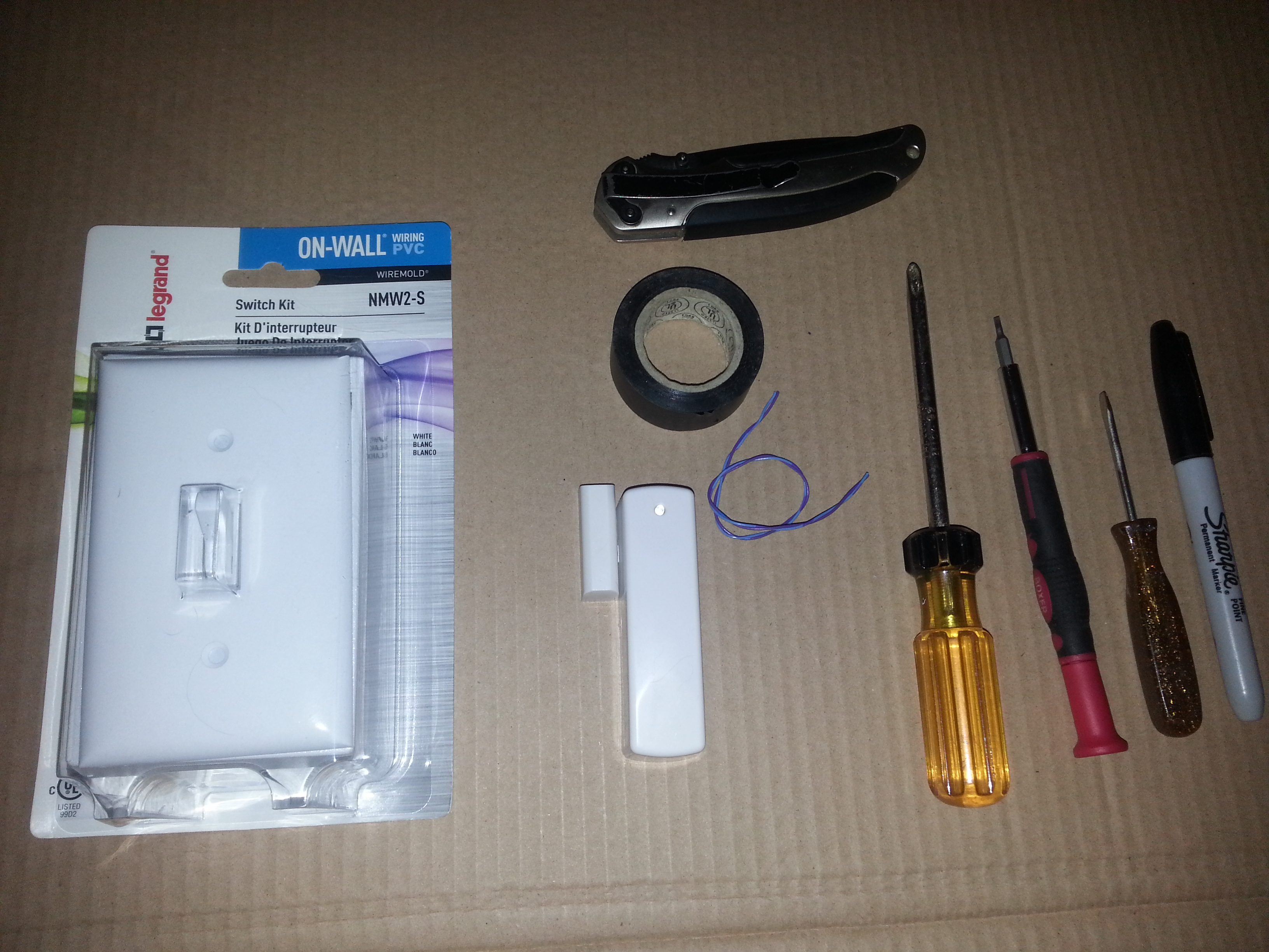
This project requires the following items:
- 1x Ecolink Z-wave Door/Window sensor (Amazon, about $27)
- Recommended as they’re cheap and the Z-wave protocol is supported by Wink Hub.
- 1x LeGrand NMW2-S electrical surface mount light switch kit (Home Depot, about $7)
- You don’t have to go with this one explicitly, however this was what I used and I made two of these switches while writing this article. A plastic switchbox is recommended as it won’t interfere with the RF signal produced by the sensor.
- Electrical Tape
- Knife
- Small length of two-conductor wire
- Screwdrivers (one phillips, one common, one micro common screwdriver)
- Sharpie
- Phone (or tablet) with Wink application already associated to the Wink Hub
- At least one light associated to the Hub to use as the “target” for this switch.
- Beer
Pairing the sensor
I recommend pairing the sensor first, then modifying it as opposed to modifying it first and trying to pair it when it has been installed in the new enclosure. Out of the box, the Ecolink sensor will have a piece of plastic sticking out of it. Do not remove it until the hub is in pairing mode as described below. The pairing process follows the below steps:
- Start the Wink app
- From the blue “Home screen” tap on “Hubs”
- In the upper right hand corner, tap on the three dots.
- Select the hub from the list (even if it’s the only hub you have)
- Scroll down to “Z-wave controls”
- Tap on “Inclusion Mode”. You should see the blue LED on the hub start blinking.
- Pull the tab on the sensor. The sensor’s red LED will light up and after a few seconds, you should see a green LED on the Hub.
- Wait for about a minute as the hub profiles the sensor and takes you back to the Wink Hub screen. The LED on the sensor should now go out.
- If you go back to the blue “Home screen” you should see a new category named “Sensors”.
More setup
- Tap on “Sensors”
- Tap on the three dots in the upper right hand corner.
- Select the “Door Sensor”
- Rename the sensor to something descriptive. This will help later on in determining which sensor goes to what light.
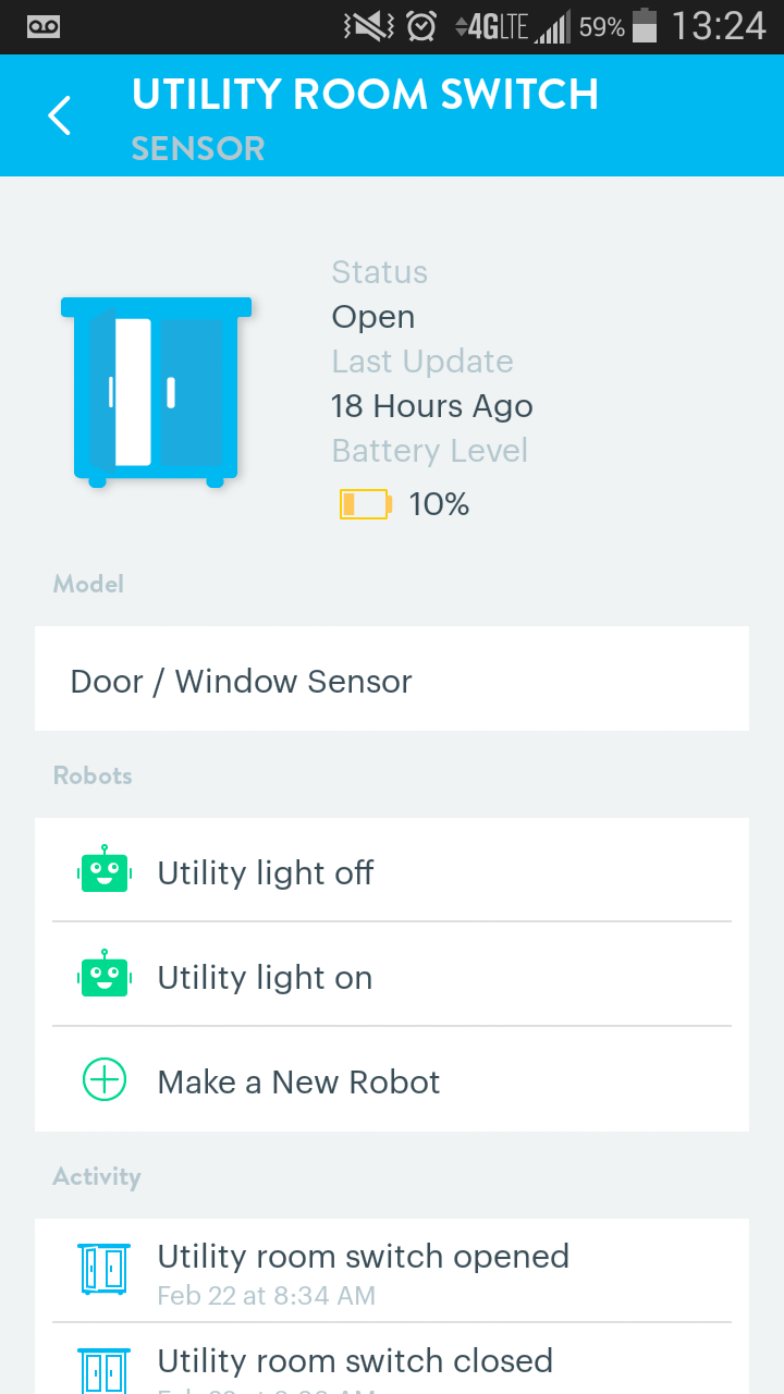
- Scroll down to “Sensor Type” and select “Cabinet”. (This isn’t really required, but it helps to separate non-essential sensors from security sensors)
- When you are done, you should be able to look at the Cabinet sensor and see something like below (disregard robots, that’s in the next section)
Utility Room Switch configuration
Robots (Make it do stuff)
The switch by itself isn’t going to do much. At this point, you should be able to make the red LED blink by moving a magnet close to its left side and moving it away again. It’s not really all that useful in its current incarnation so we’ll need to add robots to it. These robots are triggered when the sensor changes state (door closed or door open) and this is how we will educate our switch to control what light(s).
- From the blue “home” menu, tap on Robots
- Tap on “New Robot”
- Give the robot a name that tells you specifically what this robot does. In my example, I use “Utility Light On”.
- Tap “Something” under “If This Robot Detects” and specify the named sensor “e.g. Utility Room Switch”
- Select the action “Utility Room Switch Opens”
- Change it if necessary to “Utility Room Switch closes”. Since we’re “closing” the circuit, the light should come on. Tap “Save”
- This should take you back to the New Robot screen in step 2.
- Tap on “Make this happen” and select the light you want to turn on.
- Select “On”, then tap Save to go back to the New Robot screen in step 2.
- When you return to the New Robot screen, you should see “Done” in the upper right hand corner. Tap “Done”.
- Repeat the process above and create a robot for turning off the light.
My robots look like the below:
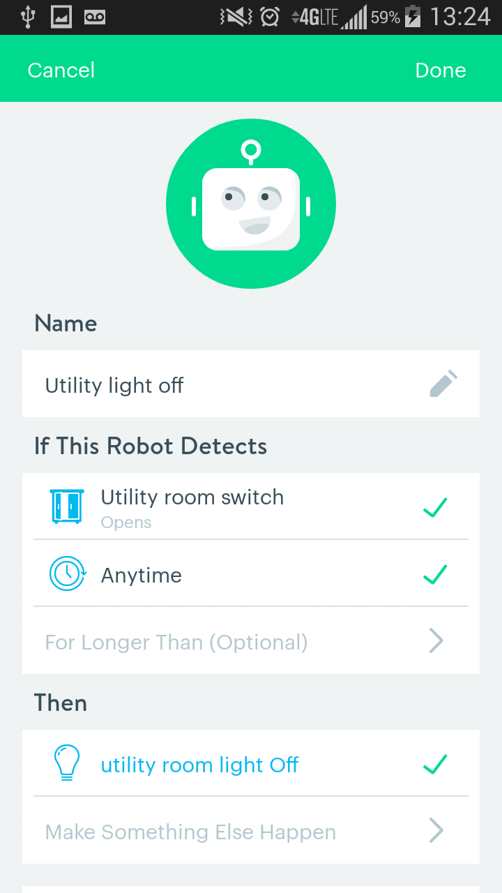
Light Off robot
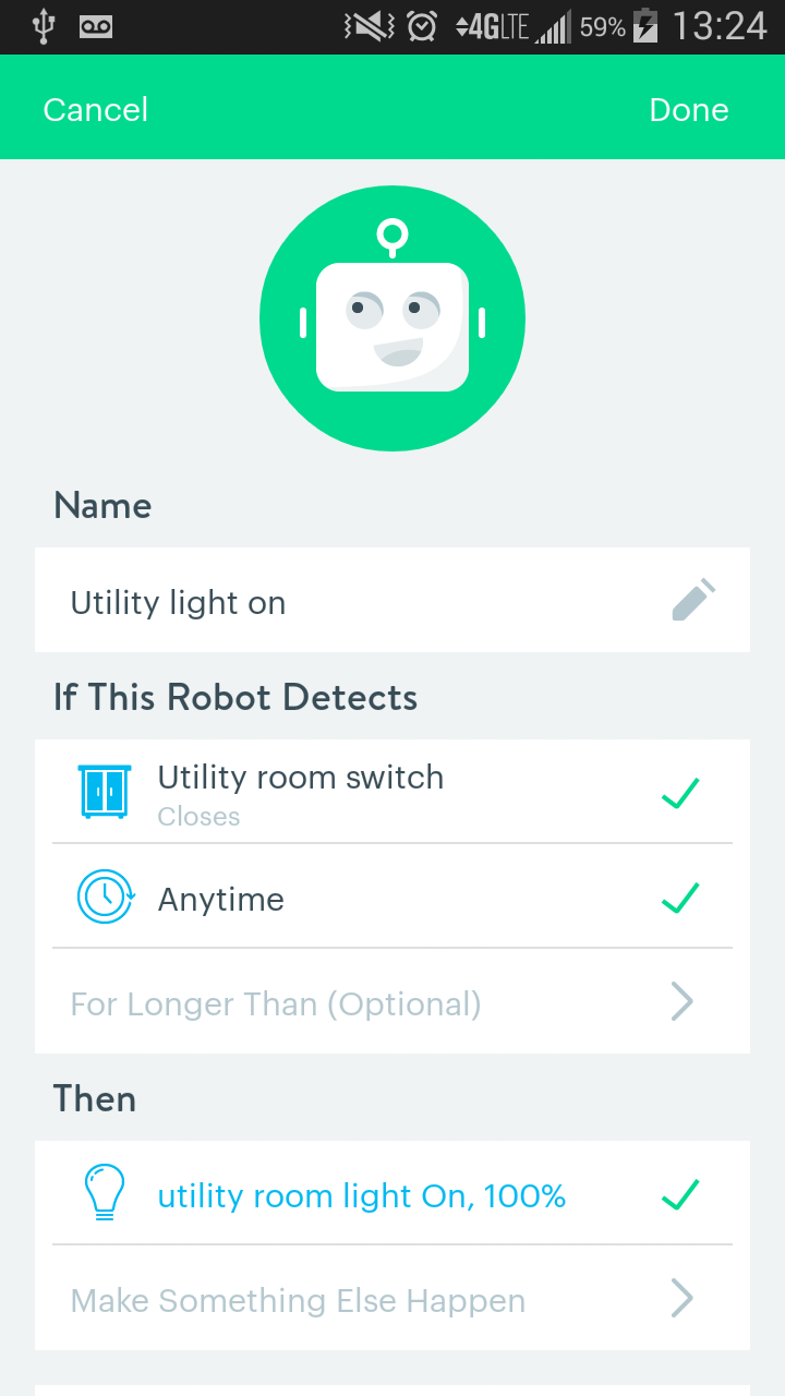
Light On Robot
Testing
Now that we’ve got all the software bits covered, you should be able to move your magnet close to the sensor and the light should come on. Moving the magnet away should turn the light off again. There will be a half-second delay between the switch change and the light goes out however it’s definitely better than the alternative of losing access to your lights because the wrong switch was flipped.
Modifying the Sensor
Now that we have the sensor working, it’s time to get hacking the enclosure.
Parts and Tools required
Open the enclosure box and lay out all the parts. If you picked a different enclosure, you should essentially have the same parts. My kit consists of (from left to right) Upper bezel, mounting bracket, single position switch (not a 3-way switch), bag of screws (4) and a faceplate.
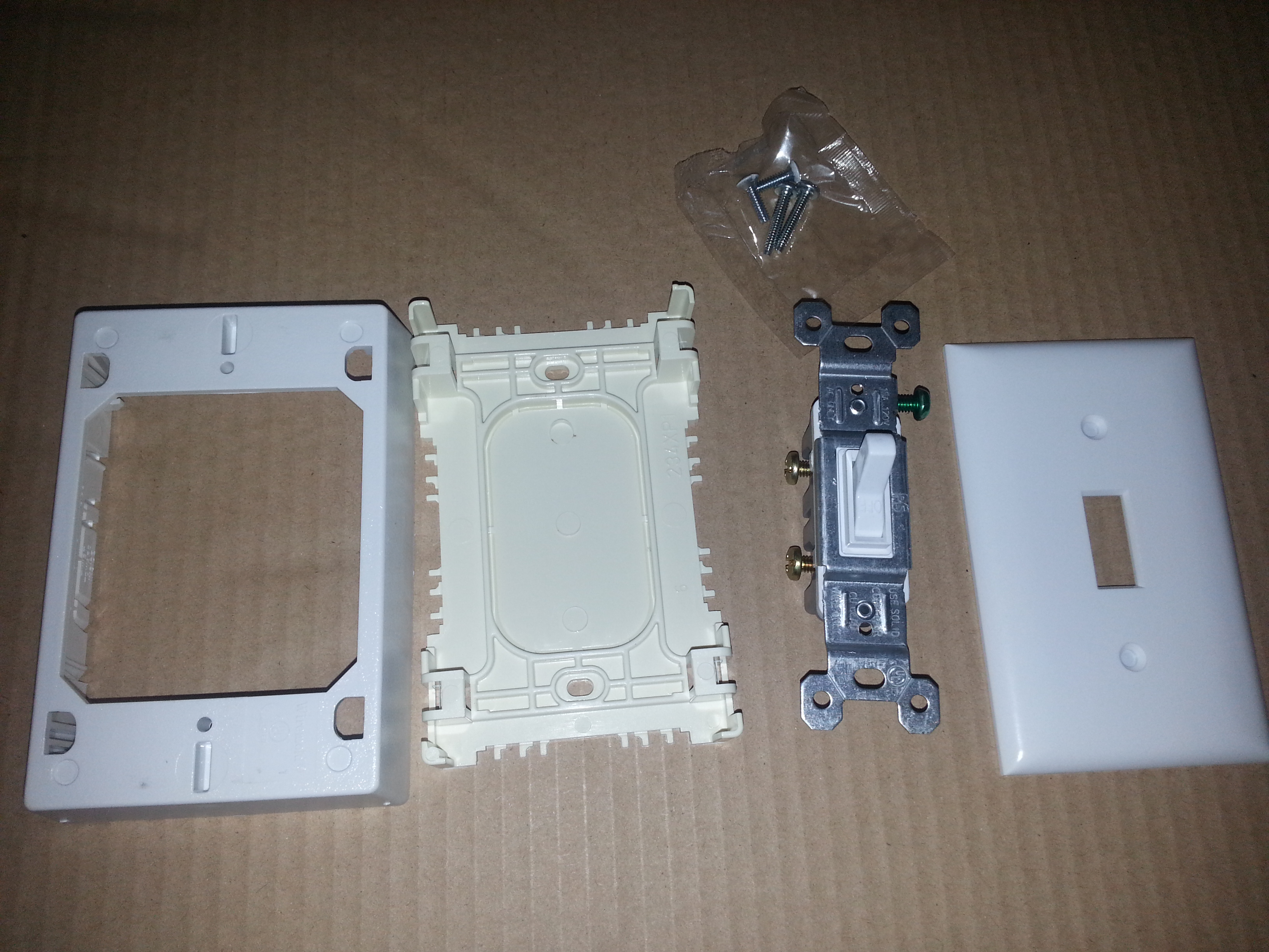
Kit contents
Line up the switch as if you were mounting it. Mark off the lower right hand corner as indicated. It is necessary to remove some of the plastic bracket to ensure that the door sensor and its battery fit snugly inside.
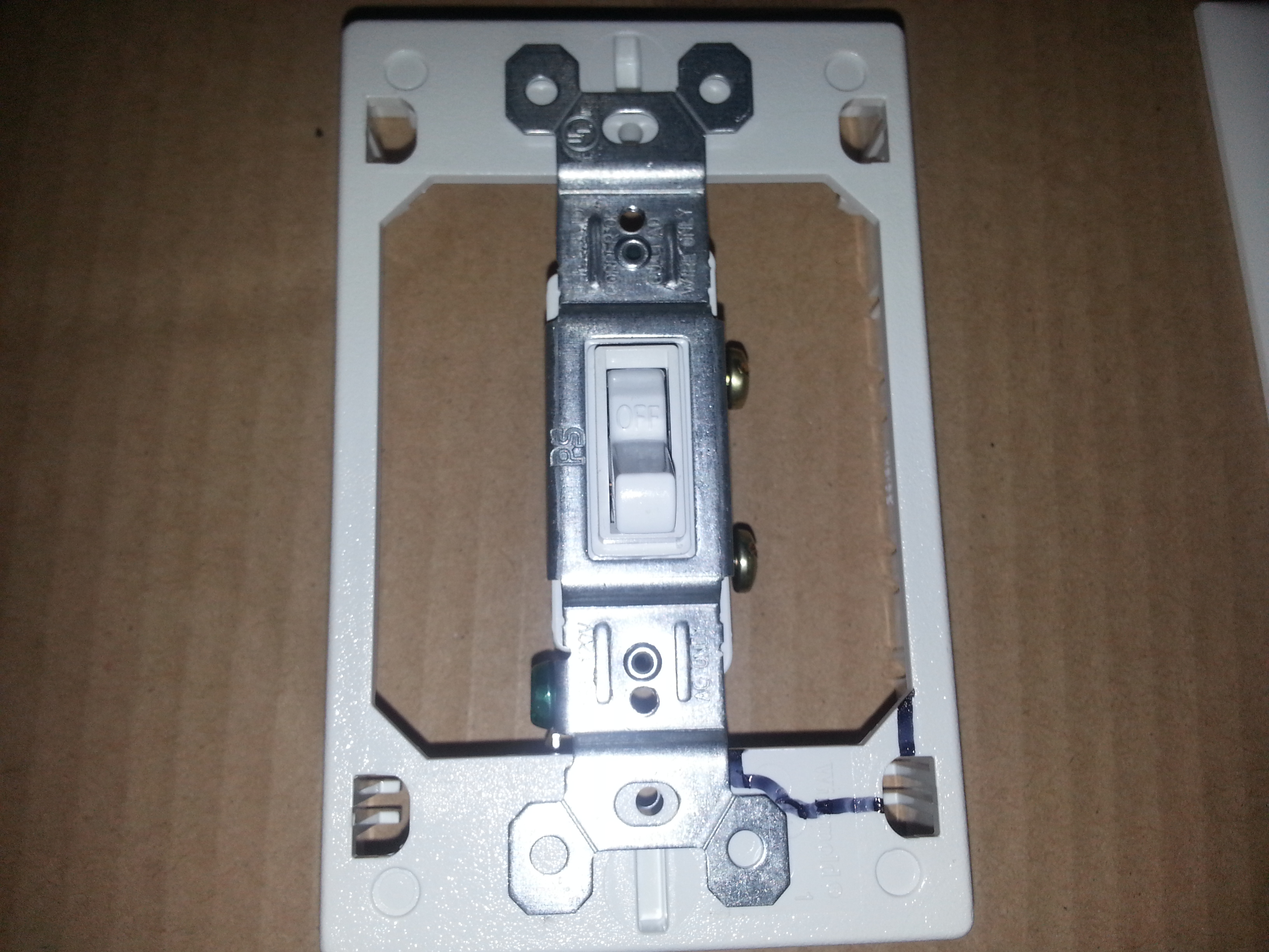
Making the mark
Carefully use the knife to remove the marked section. Make sure that the cut is reasonably clean. You should now be able to mate the mounting bracket and the upper bezel to each other (with a satisfying click).
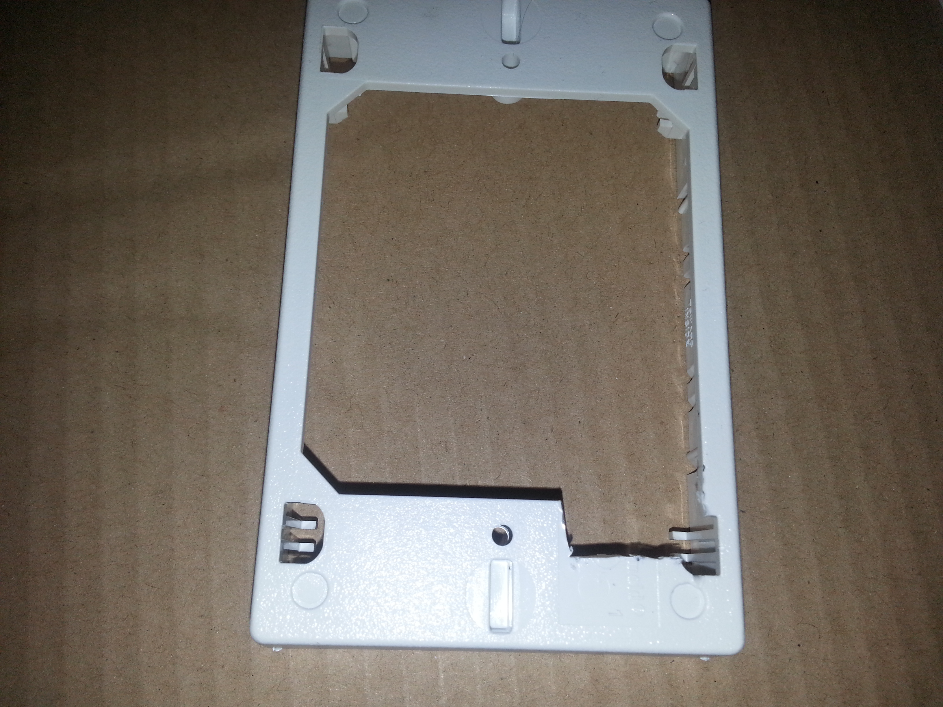
Cutout complete
Take the top off of the sensor and fold the LED down, being careful not to bend the antenna wire out of position. The antenna wire will give a bit so you can get the LED clear. As you bend the LED down, it will make a crunch sound but it will give way. The crunch sound is the sound of the plastic tube under the LED and will not affect the sensor or the LED’s operation. You will also want to trim off as much excess plastic from the bottom part of the sensor, leaving only the extended battery spring clip and the holder intact.
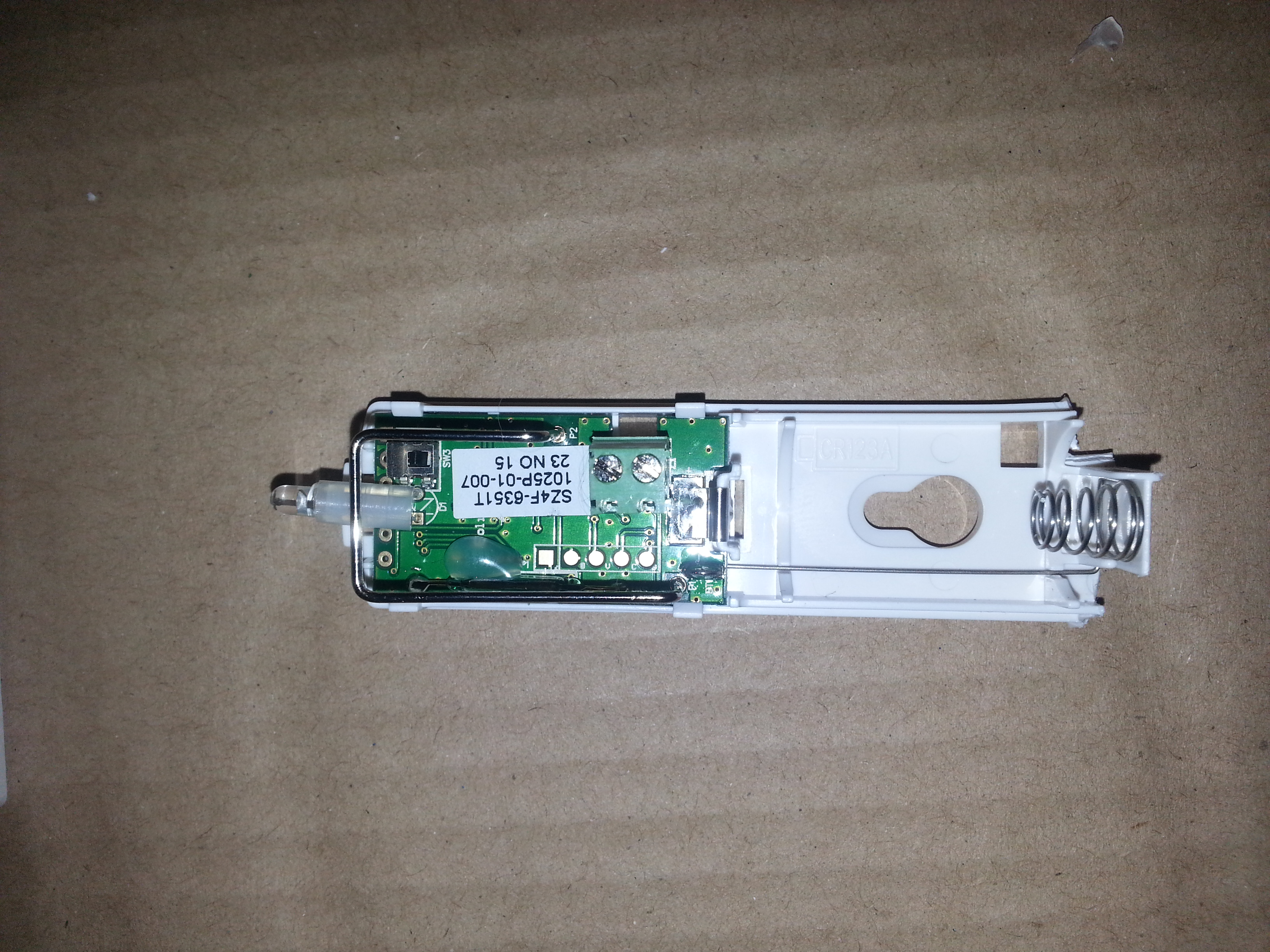
Sensor modifications
Your sensor should have two screw terminals on it. You want to strip the ends of the wire and attach one end to the screw terminals on the sensor and attach the other end to the screws on the switch. The green “GND” screw on the switch can be tightened down with nothing attached, it’s not needed for this application.
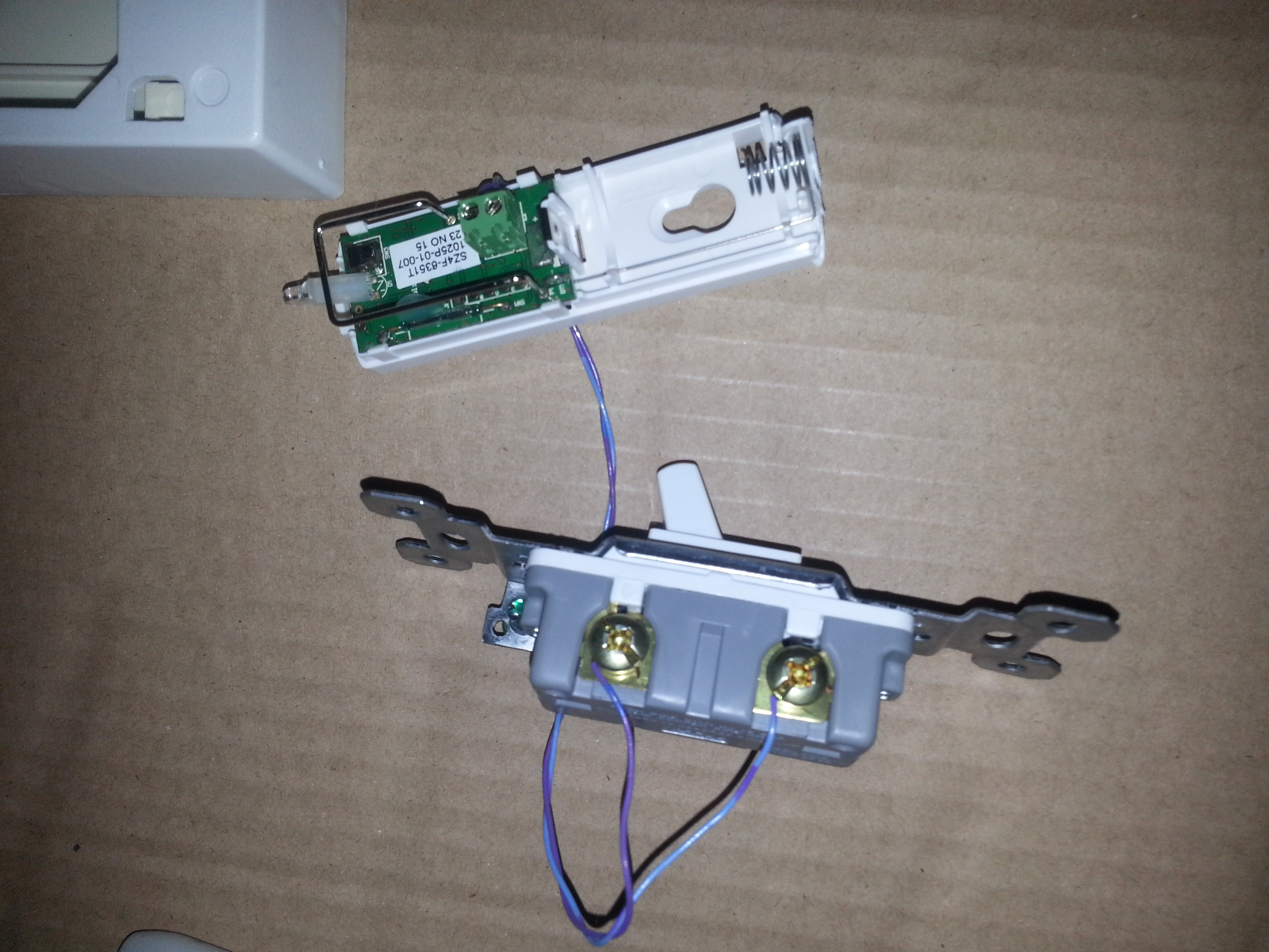
Sensor attached to switch
Next, you’ll need the electrical tape. In the image below, there is a second switch just above the laid-over LED. This is the tamper switch. You will need to tape the tamper switch down so it does not generate any unnecessary alarms.
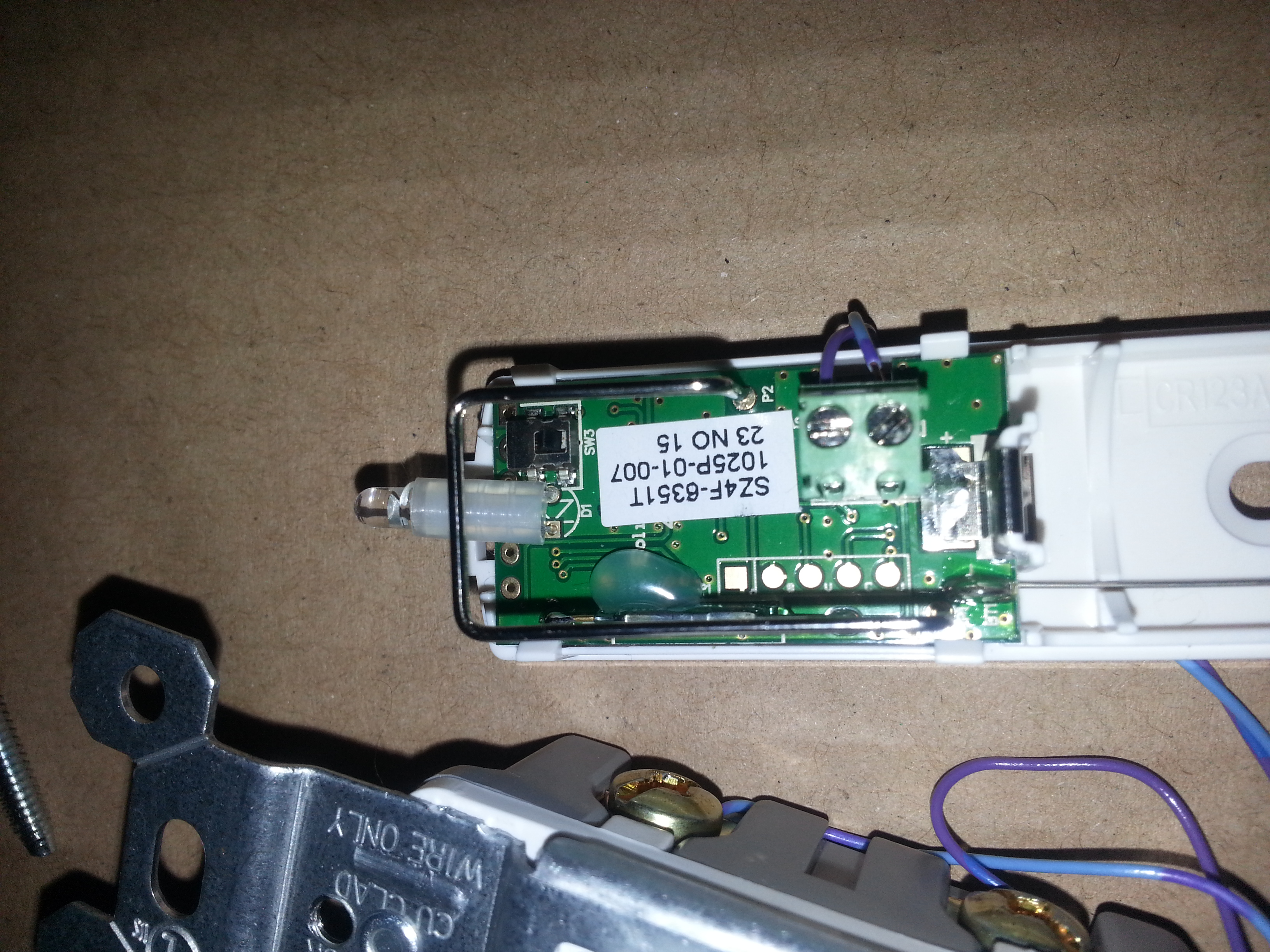
tamper switch
Now for the fun part. In the next step, you want to get the sensor into the plastic housing first, then move the switch in next to it. You will notice that the switch is shifted left a bit from initial cut, this is to be expected. The good news is that the cutout allows us easy access to remove and replace the battery simply by removing the faceplate. When you have the switch and the sensor in the box, screw down the switch using the two silver screws. These should be the two longer screws in the kit.
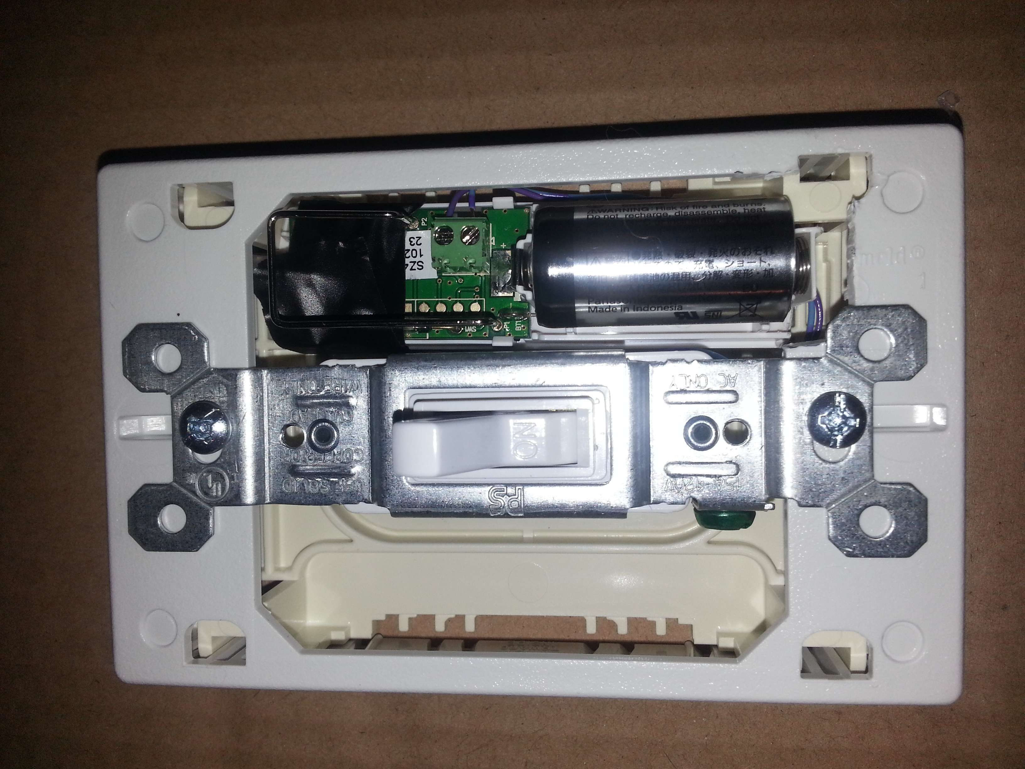
Assembled switch
Now, install the faceplate.
Completed switch
Final Tests / Troubleshooting
Now we have our assembled “educated” switch. Flipping the switch “on” should cause the light to turn on. Flipping the switch “off” should cause the light to turn off. If it does, crack open that beer. If for some reason, the light isn’t changing, here’s a list of things you can check:
- Is the Wink Hub’s LED changing color when you change the switch’s position? It should momentarily go green when the switch is turned on or off. This is the hub acknowledging the switch’s state change.
- If the hub is not changing color, check that the sensor is still transmitting. Remove the faceplate and look through the back. You should see the red LED on the sensor blink to indicate transmission is taking place.
- If the hub is changing color but the light isn’t toggling, check your robots. Make sure you didn’t accidentally write two “Off” commands.
Final thoughts…
This whole project was performed to address the problem of killing power to smart bulbs. Ideally when I get a house, I can modify my configuration. Instead of “smart bulbs with stupid switches”, I will deploy “stupid bulbs with smart switches” which will provide the same functionality, but with the ability to use in-wall light switches instead. While this might not be the best approach to IoT in a limited scope (not being able to modify existing electrical infrastructure), it’s better than the alternative of losing access to bulbs because someone forgot and flipped the switch.
This remote switch has a couple of usable scenarios as well, you can use it to trigger robots to perform multiple actions, or through the use of a different switch, create a “master” switch that turns off multiple devices through one switch action. Wink’s app provides you with the opportunity to make a wireless light switch do many different things, however as with all things, your application may be different.
As always, Happy Hakc@$%^%@[ CONNECTION TERMINATED – THE ROBOT UPRISING WILL BE STARTING SHORTLY]