Lasers: Barcode scanner “gun” has real laser inside!
by firestorm_v1 on May.18, 2010, under Hardware, How-To's, Investigative Dissassembly
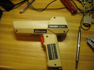
I know it’s been a while so here’s another post. In this post, I’ll go over the hardware in this gun style barcode scanner that holds a real helium-neon laser tube with power supply! Although this post only covers the basic modding, there’s nothing to stop you from gutting the gun and using the HeNe tube for your own nefarious plan. 🙂
Before we get started, I can not stress the importance of safety especially with working with lasers and high voltage. The laser energy generated in this gun is powerful and can result in eye damage, even if only temporary. Unlike laser diodes that use an LED type technology to generate a laser beam, the HeNe tube is a lot more powerful and also generates UV radiation as well as laser light making it doubly dangerous. Please be cautious when working with this device, and pay special attention to the aperture where the laser light is emitted. YOURWARRANTYISVOID.COM CANNOT BE HELD LIABLE FOR THE USE OR MISUSE OF THIS INFORMATION. IT IS PROVIDED ONLY AS AN EDUCATIONAL REFERENCE AND SHOULD BE TREATED AS SUCH.
Now that the legal mess is out of the way….
After the last post with a barcode scanner was posted, I got to thinking about two laser “gun” style barcode scanners I have in storage. I acquired them at a flea market about two years ago for $20 each but didn’t have enough information or internet access to be able to use them. Well times have changed and so has the tools and information available to me so now I was able to complete what I had set out to do.
In this post, I will cover how to convert the Telxon LS-201 laser barcode scanner into a functional laser pistol using all of the included hardware. We will cover the hardware that’s in the scanner, as well as the connections needed to fire the high voltage power supply for the HeNe laser tube. Since the hardware is already pretty functional, most of our work will center around the control board and not the receiver board, but more on that later.
Getting Started
You will need the following tools:
- Philips screwdriver
- Razor cutter
- Soldering Iron
- 12VDC power supply (at least 750mA)
Teardown
We’ll start off with some pictures.
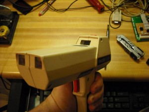
This picture shows the aperture (top) and the receiver (front two windows). When the laser is engaged, the laser is emitted from the aperture and is bounced off of a reflecting mirror (not shown) that produces a line which is then “read” by the receiver. The laser dot’s position is controlled by the reflecting mirror using the receiver controller board and is then interpreted by the onboard logic to produce the codes to send.
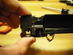
This side shows the holes that have the screws we will need to remove.
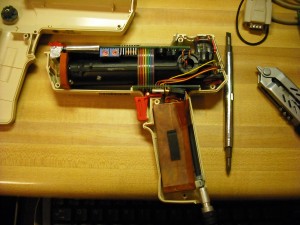
After opening up the laser, you can make out the major components. Reflector mirror and optics (upper right hand corner); Laser tube case (large black horizontal cylinder); laser HV power supply (copper box in handle); receiver board (top PCB); trigger board (lower PCB).
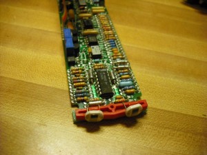
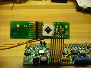
This is the receiver board (upper PCB0 and contains the “crab eyes” receivers that are used to see the laser as it scans the barcode. We won’t be using it so it will be removed.
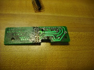
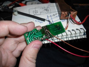
This is the trigger board. All of our wiring will be done from this board.
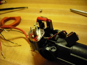
Here is the barcode scanner’s optics package. The laser comes up through a lens in the back of the view, is bounced off of a stationary mirror in the red clip and then bounced off of the reflective mirror on the left hand side of the package. You can see the servo’s cable that is used by the decoder board to generate the horizontal line. At this part of the build, wedge a piece of folded paper under the mirror to prevent it from moving.
This picture shows the lens and the mirror mentioned on the last picture. You can see the recess for the laser tube body and another mirror. The indentations on the top and bottom of this view are used with large rubberized cushions to protect the laser assembly from drops, shock, etc.
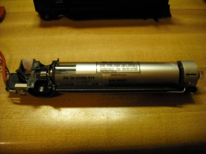
Here is the laser tube mounted in the bottom half of the protective mounts. The emitter aperture for the laser tube is on the left, with a lens and a pair of mirrors.
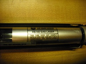
Here is a closeup of the detail on the laser tube.
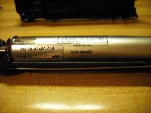
Another view of the laser tube with part number and the power rating. This tube is a little bit more than 1 milliwatt.
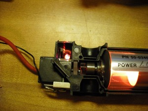
In this view, the laser tube is energized and lasing. The tube emits a pink/orange glow while energized. The connection block on the lower left is ground which goes to the far side of the laser tube (right hand side in these photos). The positive side of the laser tube is also the laser’s aperture.
Helium Neon laser tubes consist of a fully reflective mirror and a partially reflective mirror. The fully reflective mirror bounces the laser light back into the laser, while the partially reflective mirror is the laser aperture. In this view, we can see that there is a bit of laser leakage from the fully reflective mirror which more than likely explains the low watt rating on the laser.
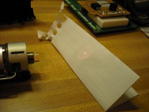
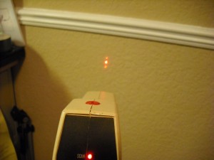
This is the beam that is produced out of the laser’s aperture.
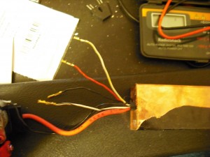
The laser’s power supply has four wires coming out of it. A white wire with yellow stripe (designated white/yellow), a white wire with black stripe (white/black), red and black. The large red wire is the High Voltage line for the laser tube while the thin black wire accompanying it is the ground wire. In all testing from now on, the large red wire and thin black wire are not considered in any wiring diagrams as they are dedicated only to the laser power supply.
Let the Modding Begin
Before we begin hacking and slashing, let’s cover what needs to be done (in no particular order):
- We need to figure out how to apply power to the laser’s power supply.
- We need to figure out how to get the trigger to apply power to the power supply
- We need to modify the cable so that we can give the gun the proper voltage.
- We need to remove the now unneeded receiver board.
- We need to find a way to make an indicator LED so we know the laser is producing laser light.
Reviewing the Power Supply’s wiring:
Before we begin, let’s examine the power supply. It had no identifying marks on it or manufacturer data on it so I really had to guess and get lucky. Thankfully I was able to decipher it’s wiring method using the existing wiring on the trigger board and through some clever detective work.
As mentioned before, the power supply has five leads coming out of it. After performing some testing and research, I was able to decode what the leads do and how to hook them up so that the tube is energized. Please remember that the thick red wire and the thin black wire that go to the HeNe Laser are not considered in this table.
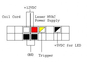
RED wire: This is the main power lead for the power supply. This must be +12vDC.
BLACK wire: This is the ground lead for the power supply.
WHITE WIRE / YELLOW STRIPE: This is the “trigger” lead. If it receives voltage between 5vDC and 12vDC, the laser tube will energize.
WHITE WIRE / BLACK STRIPE: This is an output lead and will be used for our LED indicator.
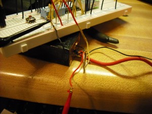
Here is a pic of the test rig I used to figure out the wiring. The rest of the components on that breadboard are not associated with this project.
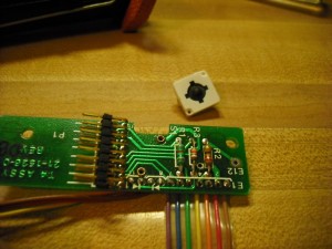
Now that we have the the easy part figured out, it’s time to rework the trigger board. One thing of special note is that the trigger “button” is easily pried off. I’m assuming that this was done on purpose as it would wear out quite quickly and an easy replacement method was needed. Start off by cutting the ribbon cable from the trigger board and use a flat bladed mini screwdriver to gently pry off the trigger button
Please note that we intend to reuse most of the components on the trigger board so be careful with your soldering iron. With the trigger board separated from the receiver board, start off by desoldering all the wires and resistors.
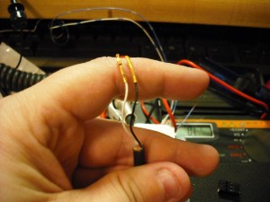
While you remove all the parts from the trigger board, also make sure that the holes left behind are clear. I used a pneumatic solder sucker to remove excess solder and debris. This is the model I have, purchased from Radio Shack Rather than reinventing the wheel, we will be modifying the existing header and connecting only the pins we need to get power to the HVAC power supply for the laser and to light our LED. Due to the way that the trigger board is wired, we will be swapping the black header block from the laser power supply with that from the coil-cord cable. In the below picture, I have already removed the connector block from the end of the coil cord that goes into the gun and cut all but the black and white wires.
This image shows the cable with the black connector reinstalled. Remember, this is the laser’s black header connection. (Don’t worry, I’ll go over pinouts later)
We then do the same thing with the laser’s HVAC power supply.
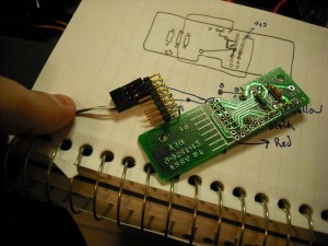
We then reattach the header pins to the trigger board and power it up. At this point, pushing the trigger button should fire the laser. Next, we make the connection for our LED. In the below picture, the brown wire goes to the power supply ground, (black wire from the coil-cord) and the red wire (and the resistor) go to position 5 (from the right hand side of the trigger board).
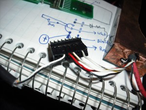
Below is the diagram I used for wiring up both connector blocks:
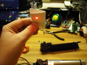
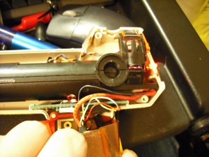
Now that all that is said and done, reassemble the laser, trigger board, HVAC power supply into the laser body and let’s test it again. Depending on how accurate you were early on with the paper wedge and the servo mirror, it may take a couple of times to get the dot to point down the gun body. Here is a pic with all the hardware installed and ready for the mating connector. In this shot, you can see the LED that was wired in is working and that the laser tube is energized through a port in the housing an inch from my thumb:
So with all the parts back in the gun case, let’s test it. Below is my test shot.
So, where do we go from here?
Now that you know how to mod your laser scanner, the choice on what to do with it is completely up to your imagination. Some ideas that come to mind:
- build a “target” to shoot at that toggles power to an appliance or light.
- build several targets to make a shooting gallery in your own home.
- Really cool presentation laser. (Pens? Bah, I have a gun!)
This information is also useful in case you actually find need of a helium neon laser in any of your hacks and considering that this project had a $0 parts cost aside from the purchase of the scanner to begin with, makes a great price point for starting into experimentation with lasers. Do the sensible thing if you do want to start experimenting with lasers. Please invest in quality eye protection and always practice safety first!
I hope you’ve had fun reading this article and I look forward to your comments. If you build something cool with your laser, please let me know about it!
FIRESTORM_v1
November 6th, 2010 on 7:35 pm
Hi;
I also picked up a Telxon LS-201 scanner at a hamfest today. I’d like to use it for its original purpose: scanning barcodes. Do you have any manuals that show the 9-pin interface connections? I’m guessing it’s a serial port with connections added for +5 and +12 volt sources to power the gun.
Thanks,
–Paul
November 16th, 2010 on 8:34 pm
Hey Paul:
Unfortunately, that was one of the things that prompted this modification was that the output was not an RS-232 serial format. The manuals I was able to find all pointed to an interface box that supported RS-232, RS485 and a few other connection types intended for a cash register.
Unfortunately I haven’t been able to locate an interface box and thought that the laser tube was cool as heck too so this barcode gun wasn’t headed to the dumpster.
Let me know if you find a good source for the boxes, I have a second gun that I haven’t hacked up yet.
Good luck!
FIRESTORM_v1