GUIDemo – A full VGA Library for the Propeller
by firestorm_v1 on Nov.19, 2010, under Embedded devices, Hardware, How-To's, Microcontrollers
The Parallax VGA GUI Demo is great for adding a pre-built GUI for your projects. The bonus is that the drivers for using a PS/2 keyboard and mouse and a VGA display are pre-built and ready to run. With a little bit of configuration, you can add a well built UI to your application and make it easier to display output and receive input from the user.
In this article, I will demonstrate some of the basic options that are needed in order to get the GUI up and running. While our application is going to be turning on a few LEDs, once you have these basics down you should be able to use this article and build whatever user elements are required for your application.
Prerequisites:
If you haven’t already, I would recommend the Parallax PS/2 and VGA Adapter board. This board provides two PS/2 ports (mouse and keyboard) and a 15 pin VGA port in an easy to use modular design that is breadboard compatible. Here is a link to the VGA board on Parallax’s site and here is the link to my earlier article.
In addition to the Adapter Board, you will need
– A PS/2 mouse (Not a USB mouse with a PS/2 adapter)
– A PS/2 keyboard (Not a USB keyboard with a PS/2 adapter)
– A 15 pin VGA monitor
– six LEDs, any color
– six 100 ohm resistors (Brown-Black-Brown)
– Jumper Wires for the Adapter board
– A PC with USB port for the PropPlug USB programmer.
– 9V Battery or other 9VDC power source
Understanding the concept of a UI
Before we get started, let’s discuss the basic differences between a Prompt and a UI.
A Prompt:
- – asks for something direct like “Your Name”
- – Reads the response, Input halts until requirement satisfied, e.g. (Press any key to continue)
- – Treats the response as programmed, e.g. $YourName
- – is programmed in a linear fashion. e.g. You prompt for your name, then you prompt for your address, then you prompt for your date of birth, etc…
A GUI:
- Shows multiple items to interact with
- Reads a response when triggered with an event and does not wait.
- Performs actions based on event triggers.
- Can perform actions in a non-linear fashion. e.g. Clicking Button 1, Button 3, Button 2, Button 6, Button 1 again.
Remember, although a GUI can contain prompts (“Click OK to Continue”), it’s not often that a prompt becomes a GUI. Also remember that a GUI is Event driven, not prompted.
Events
It’s important to understand that performing any action with the mouse and keyboard triggers an event. It’s when the event (in most cases, a mouse click) occurs on a GUI element (a checkbox for example), we get something to happen. By programming the Parallax GUI Demo, you will build GUI Elements (things to click on or type into) using Mouse and Keyboard Events in order to generate some kind of output (Lighting LEDs).
Keep this in mind, as generating events and how to deal with them are the cornerstone of any GUI programming (not just Parallax!).
Elements
Mouse events are nothing without something to interact with, so that brings us to the point where we have to talk about the GUI. Each object in a GUI, checkboxes, menu items, windows, submit buttons, etc. are all considered elements of the GUI. We build the GUI using elements to satisfy our program’s needs. For the “What is your name?” prompt, we would need a window element (with a Window Title element), a text element saying “What is your name?”, a text field element (so we can get the name back to the program) and a submit button element. That’s Five elements! Thankfully, only two of them are interactive. The text field needs to be clicked on (to tell the GUI that keyboard input goes here), and the Submit button needs to be clicked on to tell the program to continue.
Even though we started out with five elements, thankfully we only have to code for two events.
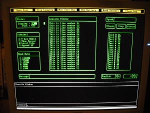
Below is a screenshot of various elements that the Parallax UI is able to generate.
In this screenshot, we can see the following interactive elements:
– Spin Boxes – A single element with up and down arrows that allow you to select from a list of predefined options. (like a Page Count field on a Print window)
– Checkboxes – A listed series of predefined options that allow for multiple options to be selected.
– Radio Buttons – A listed series of predefined options that allow only a single option be selected.
– Pushbuttons – A single element that is clickable (like a submit button).
– Menu Bar – A horizontal element containing multiple pushbuttons.
– A Text Input field – Another horizontal element that takes input from the keyboard.
We also see the following non-interactive but still needed elements:
– Windows – We need windows to keep these elements organized, otherwise it doesn’t work too well.
– Status Lamps – Think of these as the GUI equivalent to an LED and resistor. They can be toggled on or off.
Now that we know what all the elements are, let’s do something.
Getting the hardware ready
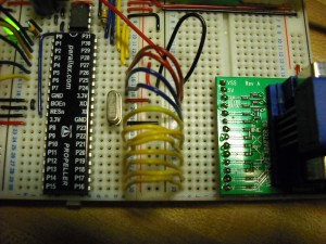
Connect the 15 pin VGA/PS2 breakout kit to the lower right hand corner of the breadboard as shown in the image below. The breadboard should be oriented as shown with the PropPlug mounted on the top, usb cable pointing right. You can then connect the 12 pins straight across (watch out for the crystal) to the 12 pins on the right hand side of the Propeller (P16-P27). Attach the Vss lead to any of the Vss busses (black lines) on your breadboard.
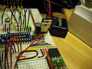
In order to get the required +5V for the PS/2 mouse and keyboard, look closely at the two voltage regulators at the top of the board. There is an LM2940 (back regulator on the picture below) that provides the 5V and a LM2937 (front regulator) which provides a 3.3V source for the Propeller. Be sure to attach to the OUTPUT of the LM2940 as shown in the picture below. As a hint, my wire is in the third horizontal row from the top of the LM2940 which is its output lead.
DO NOT CONNECT YOUR +5V LEAD TO THE +9V BATTERY OTHERWISE DAMAGE TO THE PROPELLER, MOUSE AND KEYBOARD MAY RESULT.
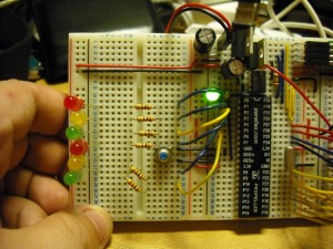
After you have the VGA adapter connected, hook up the LEDs so that the cathodes go to ground and the anodes run through the 100ohm resistors to P0-6 as shown below.
Get the software
If you haven’t already done so, download the VGA Text GUI Demo from here: http://obex.parallax.com/objects/413/
Unzip the archive, load it up in your Propeller Tool application and load it into RAM to save write cycles on your EEPROM. If everything works properly, you should be able to move the mouse, click on things and be able to type text in to the “COMMAND” field at the bottom. Play around with it for a bit and get used to how the elements interact with each other. If you want to ensure that your wiring is correct, read the GUIDEMO and GUIBASE section below.
Before proceeding, it’s recommended to make a backup of the unzipped Propeller VGA demo so that you will have something to refer to in case you accidentally delete part of the demo application. Load the copy of the code for the next step and leave the original copy untouched.
Hacking up the Code
Now that you’re up and running with the test code, let’s take a look at the existing code and start modifying it. We’ll cover important aspects of the existing code along the way. In our application, we will be using the UI to draw a simple window containing six checkboxes that correspond to the six LEDs we have installed. Once finished, when we check a box, it will light the corresponding LED. If we clear that checkbox, it will extinguish the LED.
So let’s get started.
GUIDEMO.spin
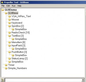
The GUIDemo.spin file is considered the “Top Level” or “root” (if you’re a Linux admin like I am) of the entire application. This file references sub-codebases through an OBJ (Object) declaration. Although Parallax called it Top Level, I have always referred to it as the “root” as in the root of the project much like the root of a filesystem.
Without getting into the syntax of Spin (the Propeller coding language, a topic that Parallax is much better suited for than I am) just know that this is the trunk of the tree as far as all other pieces of code in the VGA Demo are concerned.
Starting at the top of the GUIDemo.spin file, you see a secion labeled CON. This is for the constants that GUIBase uses to initialize the PS/2 mouse and keyboard and the 15pin VGA port.
The vga_base should point to the I/O pin that is connected to the “V” pin of the PS/2 VGA adapter. The GUIBase will assume that the rest are mapped accordingly. If you are using something other than the Parallax adapter, you will want to ensure that your adapter is wired up as shown below:
I/O Pin Function
P16 V – Vertical Scan
P17 H – Horizontal Scan
P18 B0 – Blue Positive?
P19 B1 – Blue Neutral?
P20 G0 – Green Positive?
P21 G1 – Green Neutral?
P22 R0 – Red Positive?
P23 R1 – Red Neutral?
* Please note, the ?’s mean I’m not certain on polarity, but I am sure on the grouping. The reason is that I only have the Parallax VGA adapter so I haven’t tried to fabricate my own adapter.
The mouse and keyboard each require two pins, “dat” and “clk”. The Parallax Adapter has each pin’s function silkscreened onto the adapter’s PCB for easy connection and are mapped as shown below:
I/O Pin Function
P24 Mouse Data
P25 Mouse Clock
P26 Keyboard Data
P27 Keyboard Clock
If you’re using Parallax’s VGA adapter, then make sure that your values match what is shown above. If you are using another adapter, make sure that the values match your respective device’s pins.
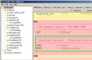
The OBJ section is where we declare any additional code that needs to be included. In the original code, you can see there are three objects declared (GUI, TMRS and NUMS) however for our program, we only need the first one (GUI). Delete the two lines starting with TMRS and NUMS highlighted in the green square in the image below.
When it comes time for you to add your own routines, you can include them here by defining them as objects. For now, just scroll down to the next section.
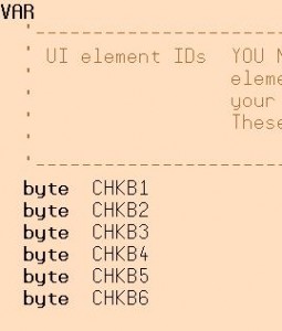
The VAR section is important because the code shows that all of the interactive elements in the GUI require a byte be assigned to them. This is important as this is how the GUI keeps track of what element is called when an event is triggered. It is critical to remember when you are designing your own GUI, that each interactive element has it’s own unique ID. This will be important later when we tie the elements into events. For now, remove all the declared bytes and add the below in it’s place:
In the above image, we are declaring six CHKB elements numbers 1 through 6. The naming convention is important as there is code later on where these get defined.
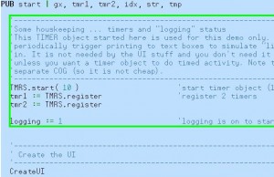
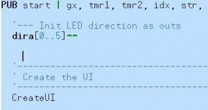
Scroll down to the PUB statement below. This section is the actual code of the program and where we will be doing most of the editing. First off, make sure that you can see between the CreateUI statement and the PUB statement (top of the blue section of code as pictured below. We will be removing the code there as it was used with the timers code object (that we removed) was initialized at start. Just like before, delete all the code within the green box. It’s not needed and will generate errors if you attempt to compile it.
We will replace the deleted code with our own code. This is the initialization code for our application and occurs prior to the GUI being set up. All our code does is ensure that the first six I/O pins (P0-P5) are set as outputs and are set low so that the LEDs are off.
When you are developing your own program, be sure that the initialization code occurs before the CreateUI statement for best results.
At this point, we have removed excess objects from our code and declared six variables for our checkbox elements and we have initialized the LEDs. Now we will tell the application what to do when an event has been triggered in order to get the LEDs to light up.
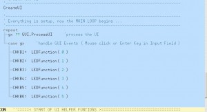
If you look at the code, you will notice that it is a very large repeat loop that contains a case loop inside it. The way it works is that the Propeller will constantly evaluate GUI.ProcessUI. When evaluated, it will check gx against the list of elements and if gx matches a defined element ID, it will then perform the appropriate action.
For now, start at the line that reads “case gx” and highlight the text down until you get to the “START OF UI HELPER FUNCTIONS”. Since we are not using the demo code in our application, we can safely remove it.
Once removed, add the code in the below image to tie in the events with our custom function. (We’ll write it next).
In the above code, we are calling LEDFunction with a different parameter corresponding to each of the six LEDs. Now we need to write the function LEDFunction so it actually does something.
In your application, you may end up writing all of your code in another .spin file and then using an OBJ to declare it. If you do that, then you can reference your OBJ functions instead of using a basic function here.
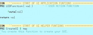
Start off by copying that CON statement and inserting it into the empty space. This will create a line we can use when reading the code to make it easier. Change it from “UI HELPER FUNCTIONS” to “UI APPLICATION FUNCTIONS” and add the below code as shown.
In this section of code, we will write our function for the events. All we are doing is taking the function’s parameter and inverting it’s existing value. If it’s 1 (on) it is then set 0 (off) and vice versa. Although we return the value of the I/O pin, it is not used elsewhere and will get overwritten elsewhere.
Scroll further down and we finally get to the CreateUI function. This is where the UI gets built and the bytes for the elements earlier get defined.
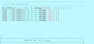
We can see that there are a lot of commands listed here. Don’t let that intimidate you as we are going to remove most of them. Find the line that starts off with “vga_cols” and highlight all the way down to the MIT License. Remove the code and add the code in the picture.
This code draws out the Text box for our project and gives it a text label. Don’t worry about the syntax, we’ll cover that in the GUI CODE section later.
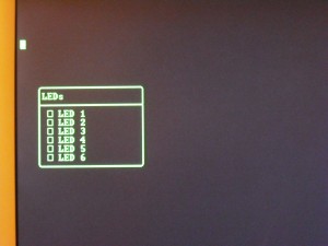
Basically what happens here is that a Simple Box (SBOX) gets drawn with the title of “LEDs”. Inside that box, six checkboxes are drawn, each with their own text description. Pretty straightforward on the UI, right?
We’re almost done and ready to test our new GUI.
GUIBASE
Now, there’s one more thing we need to do before we go loading this project into RAM and seeing if it works. We need to make an edit to GUIBase.
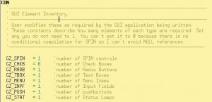
At the very top of GUIBase, in the CON section, you can see that there is a note describing the GUI Element Inventory that must be present. We need to edit the code and tell GUIBase that we’re only using six checkboxes. However, as the note describes, we can’t just go set GZ_CHKB to 6 and all others to 0, as this would throw a compiler error.
Go ahead and set all of the GZ_ variables to 1 except for GZ_CHKB which will get a value of 6 since we have six LEDs as shown below.
Once modified, be sure to save your work and then go to “Run”, Compile Top, Load RAM. You should get something like the below image on your display.
If all went well and you didn’t get a compiler error, you should get this GUI. The little green square is the mouse cursor. Go ahead and try it out. Make sure that checking each checkbox lights up an LED and that clearing the checkbox turns it off.
Now that we’ve got a working GUI up and running, let’s review what all we did aside from removing a lot of extra stuff.
- We declared a byte for each GUI element.
- We added initialization code.
- We added a declaration in the main loop to handle events from the UI to point to our function
- We wrote a function that did something based on the events we had given it.
- We updated GUIBase with the element count so that the GUI code knew how much it had to work with.
These are the fundamental steps for creating a UI with the propeller using the GUIBase code. Now that you understand the basics as far as what is required, let’s take a look at some other stuff you can do too.
Looking further into the GUI Code
In the GUIBase.spin file, you can find the code required to draw the various elements of your GUI. Reading through the code, most of the options required are in terms of position. For example, the code for the simple box (window) shown earlier, required an X and Y coordinates (in rows/cols) to place the upper left hand corner of the UI, then the width and length of the box and a title. The Checkboxes each required an X and Y coordinate, then a text length and finally a label.
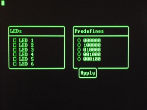
If we were to use a Radio Button group, we would need to provide an X and Y coordinates, a text length, a text label and a Group ID. The Group ID is used to associate the radio buttons together. Below is a screenshot of my implementation along with an Apply button:
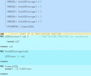
In the above code, you can see that I have established five radio buttons (RADIO1 to RADIO5) in addition to PUSHBTN1 pushbutton. These are set up in the main loop below:
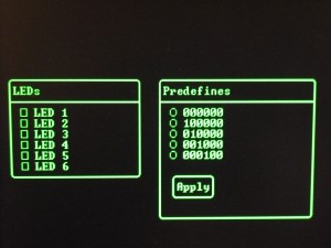
In the above code, you can see that the SetLEDStorage passes a number which gets stored in LEDState. When the Apply button is pressed, CommitLEDs takes LEDState and sets the six LEDs to the binary value of whatever was in it. Below is what the UI looks like:
Just like adding the checkboxes, I followed those same steps here:
- – I declared my additional UI elements’ GUID bytes (RADIO1 to RADIO5), my Radio Button group (RBGID1), my pushbutton (PUSHBTN1) and my LEDState variable.
- – I added my init code (setting LEDState to 0, not pictured)
- – I added routines for my elements to call user functions. (SetLEDStorage and CommitLEDs)
- – I declared the routines so that they did something (stored the LED value, applied the value to the first six I/O pins)
- – I updated GUIBase.spin with the new list of items ( added five radiobuttons and one pushbutton.)
Give the code a try and you will see that while the checkboxes set the LED state instantly, the radio buttons do nothing until they are applied with clicking on the Apply button. This is important because as you design your GUI, you will need to decide if something must happen when the mouse is clicked right then (immediate action) or if the action will get applied later on via an “Apply” button. This is entirely up to you and there is no need to do things only one way. Either method works but whether or not it works properly for your application will be your choosing.
Tips and Tricks, and things to watch out for
While developing this article, there were a couple of things I came across that you may want to watch out for. Don’t worry, you won’t blow up your Prop if you make a mistake in coding, however there are a few things you may want to keep an eye on:
- – Load to RAM, load to RAM, load to RAM and check your battery.
In my writing this article, I found out real quick that driving a display, mouse and full size keyboard will drain a 9V transistor battery very quick. A symptom of this drain is the Green LED that is present on the Propeller Education Kit. If it starts to pulse and your monitor loses sync, it’s time for a new 9V or consider a 5V USB power cord. Also, to save write cycles on the EEPROM, load to RAM whenever possible. Your computer’s hard drive is more suited to incremental saves, EEPROMs are not. Only save to EEPROM when you are ready to test your application in real life. - – There is no boundary checking. If you overlap your windows, then there is no going back. When in doubt, you can use the Mouse code to print the mouse coordinates on your project to help you identify and troubleshoot positioning. Remember that all GUI elements start by defining the upper left hand corner of the element. You will need to include the NUMS object (SimpleNumbers.spin) and the code from the original GUIDEMO.spin (lines 314 to 316) in order to have it show up. You can see an example of the boundary overlap in the below image.
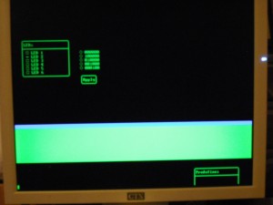
- – There is no off-edge boundary checking either. If you are setting a text field too far right of the video display or too far down, it will get cut off and your entire GUI will not work right. In this case, I set the Predefines window to X40,Y75 and 25 columns wide which was out of the limits of the current VGA resolution. The below image was the result and my UI only partially worked. Resetting and reloading RAM fixed it.
- – Also as demonstrated in the image above, UI elements are not bound to the window you create them under. Assuming that both windows were same size and I mis-typed the coordinates, the Apply button could very easily show up under the checkboxes instead of the radio buttons leading to a confusing display. You will want to make sure that your UI elements do not overlap at all as this could affect how the UI interprets your mouse actions.
Last Thoughts
There is so much you can do with the Propeller UI to make your applications more interactive. With little work, you could build something like a serial terminal and embed your project in an LCD monitor or you could make a basic home automation system with a touchscreen LCD and a wireless transceiver. The possibilities are endless and with the Propeller, you can now use full GUI capability with keyboard and mouse support.
As always, Happy Hacking!
FIRESTORM_v1


February 22nd, 2011 on 7:06 pm
Cool man, this controller is great to use with embed project.
September 3rd, 2011 on 7:08 am
It won’t sync up with my monitor.
September 9th, 2011 on 12:52 pm
Hello Gary:
One of the key things when you start working with it is to ensure that your VGA monitor syncs on green. The Parallax VGA GUI demo automatically starts up with a display resolution of 1024×768 so any recent CRT-style and any LCD monitor should be able to pick it up easily. The pictures used in this article were shot on an older LCD monitor and it rendered correctly. Older CRT monitors or purpose-designed monitors like those used at point of sale terminals usually have a lower resolution limit and may not work. I have a 10 inch POS terminal monitor which the GUI Demo does not render at all. When in doubt, try a different monitor and check your pin configuration to make sure. You may also want to consider the dual PS2/VGA Breadboard adapter that Parallax is selling. (Reviewed here. )
FIRESTORM_v1
December 2nd, 2015 on 8:41 pm
Hi FIRESTORM_v1,
The VGA Text GUI Demo link is broken:
http://obex.parallax.com/objects/413/
Can you point me to the new location?
David
April 16th, 2016 on 6:47 am
The code is no longer available at the given location in OBEX. do you still have it?