Networking: Duplicating Drops in structured wiring
by firestorm_v1 on Jul.29, 2011, under Hardware, How-To's, Networking
Structured wiring in businesses and the enterprise are as expected as the sun shining and a regular paycheck, however in the home a structured wiring solution can be an unexpected gift from the Gods of Ethernet. While structured wiring in an apartment complex is usually done central to a utility closet or shelf, sometimes the central point isn’t always convenient for your router or you find yourself needing to run multiple networks. In this tutorial, I will show you how to turn one structured wiring drop into two drops for carrying two different network segments, something that can be of benefit should you ever need it.
What these splitters do and what they don’t do.
Before we begin slicing up cables, it’s important to understand what is going on here so you can decide if this will work for you. Generally speaking, these splitters can be used if you want to carry two different networks over the same drop. If you are simply looking for more connections to your home network, and you are not doing anything special, you will more than likely want to save some time and get a mini-switch instead. Here’s a good rundown of some scenarios of why you should and should not consider these splitters:
These splitters would be a good idea for the following scenarios:
- Moving your router from the default ingress point. In my case, the central “panel” is in the utility closet, but I want my router on my desk. I use the “1” portion of the splitter to transport the WAN segment to the WAN port of my router, then use the “2” portion of the splitter to transport the LAN segment to a mini-hub in the closet to activate the rest of the jacks in the house.
- Moving a “hostile” segment or Guest network to another location. An example would be having a router installed at the ingress point and using a splitter to transport a “Guest Network” and a “LAN” connection via the same drop. In this case, the Guest Network feeds an open access point, while the LAN feeds a desktop computer. In this application, the Guest Network is kept physically separate from the LAN via the splitters but allows you to position the access point somewhere more convenient while maintaining the availability of the LAN.
- Transporting two Ethernet drops to a managed switch located in a central closet. An example for this would be to allow per-port monitoring and administration of both drops individually as opposed to using a mini-switch which would force you to perform the change across all devices attached to the mini-switch.
These splitters would not be a good idea for the following scenarios:
- Creating more Ethernet ports for the same network and you are not using a managed switch. If you are plugging two devices into your LAN at the same location, just use a mini-switch and save yourself the trouble. There’s no benefit to using splitters in a non-managed switch environment. Additionally, you may incur additional costs with having to buy an additional mini-switch to split the connections off at the central panel anyways.
- You are using Gigabit Ethernet and do not want to drop the line speed in the location you are looking at.
- You are using Power over Ethernet at this location and do not want to move the power supply.
A little bit on structured wiring and Ethernet standards
In a structured wiring environment, a “drop” is the term for a 4 pair (8 wire) cable run through ceilings, walls, etc from a faceplate with proper termination to a central wiring panel with proper termination (usually a patch panel of sorts). It’s called structured wiring as the wiring is usually planned out first with attention to detail and locations of equipment like access points, computers, etc. Generally speaking, if you are in a structured wiring location and you see an RJ-45 jack marked “Cat-5” this generally means that it’s an Ethernet jack and that the cabling and connectors comply with the Cat-5 standard.
Speaking of wiring standards, you may want to take a look at this link which provides more detail into the wiring convention commonly used in structured wiring for Ethernet networks.
In standard 10/100 Ethernet cabling that uses an RJ-45 jack, you have two wires(a pair) for transmit and two wires(a pair) for receive. In most locations, the extra two pairs (four wires) are simply left idle and untouched. In rare situations (at least in residential equipment) these extra pairs are used for Power over Ethernet which use these spare pairs to deliver power to a network device where it is not convenient to use a standard “wall-wart” power supply. This requires special adapters (not unlike our splitters) to send power and network connectivity over the same drop, then split it again at the device end. As mentioned before, if you are using PoE to feed a device using a drop that you need two connections for, you will either need to move the PoE power supply to another location or use our splitter elsewhere.
Unfortunately, Gigabit Ethernet requires all four pairs be used for sending and receiving at Gig-E speeds. If you are not willing to move the Gig-E device and are not willing to drop the speed to 10/100 , you will need to use the splitter elsewhere.
Do the Splits!
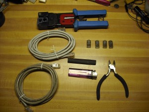
In order to pull this off, you will need the following:
- Two Cat-5 patch cords
- A RJ45 crimper
- Four RJ45 Crimp Ends suitable for the wire in your patch cords. (more if you are new at this, just in case)
- Heatshrink that is big enough to accommodate twice the diameter of your patch cords.
- Lighter
- Diagonal cutters
- Sharpie (not pictured)
- Cat-5 tester (Optional, not pictured)
- Cat-5 Female to Female junction adapter (optional, not pictured)
To start off, cut one CAT-5 end off of your patch cord and determine how far back you want to strip the jacket off. In my example, I wanted this splitter to go next to a managed switch where the ports are close together so I used about 8 inches which leaves about 4 inches for each “branch”. If you are using a pocket switch and a computer, you may want to use one foot (12 inches) which leaves you with two 6 inch branches.
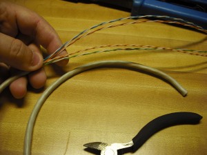
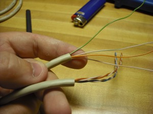
Start snipping the jacket of the patch cord, paying close attention to not damage any of the wires underneath. If you do snip a wire, cut the rest of them at the same length and repeat the process. Once you have managed to snip the jacket clean, begin pulling the jacket off of the cable in one piece. When completed, you should have eight wires similar to the below picture.
Split the wires into two groups. Separate the White/Blue and the White/Brown pairs from the White/Green and White/Orange pairs. Slip the heatshrink tube over all four pairs down past the cut jacket.
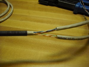
Fold the stripped away jacket in half and cut at the half line. Slip one piece of the jacket over the White/Blue and White/Brown pairs, and thread the White/Green and White/Orange pairs through the remaining piece of the jacket. Use the image below as a guide.
Slide the two jacket pieces down as far as they will go, then push the heatshrink tube at least one inch past the split. This will toughen the split to ensure it doesn’t fall apart with use. Use the lighter to shrink the tubing around the three pieces of jacket.
Now for the fun part. At the ends of the two pieces of jacket, you now have one piece with a White/Blue pair and a White/Brown pair and another piece with White/Orange and White/Green. We need to put ends on these wires so we can start using them. Start off by spreading the wires out and untwisting them like in the image below.
Trim the wires so that there is approximately one inch sticking out of the jacket and make sure that the wires are laid out like so:
- Solid Green (or green with white dots)
- White/Green – white wire with green stripe
- Solid Orange (or orange with white dots)
- White/Orange – white wire with orange stripe
The important part is when you insert them into the crimp end, the solid green wire must go into position 3, and the rest will go into positions 6, 7 and 8 as shown below. Please take note that the orientation of the RJ-45 crimp end is that the spring clip is pointing towards you, and the wiring enters from the left.
- Position 1 – Blank
- Position 2 – Blank
- Position 3 – Solid Green
- Position 4 – Blank
- Position 5 – Blank
- Position 6 – White/Green
- Position 7 – Solid Orange
- Position 8 – White/Orange
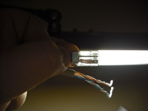
Before you crimp the RJ45 onto the wires, hold the whole thing up to a bright light and ensure that the wires are long enough to hit the end of the connector. Sometimes, a bad crimp can result if the wires are too short. Use the below image as a reference and take some time to make sure your wiring is correct. If all looks good, go ahead and crimp!
Now for the White/Blue and White/Brown pairs, you must perform the same process, except this time we will use White/Brown in place of the White/Orange pair and the White/Blue will substitute the White/Green. Our wiring diagram will change to below:
- Position 1 – Blank
- Position 2 – Blank
- Position 3 – Solid Blue (or Blue wire with White dots)
- Position 4 – Blank
- Position 5 – Blank
- Position 6 – White/Blue
- Position 7 – Solid Brown (or Brown wire with White dots)
- Position 8 – White/Brown
Do the same inspection as you did for the first crimp and check, recheck and crimp your second connector. Mark the crimp with the White/Orange and White/Green wires as “1” and the other crimp with the White/Blue and White/Brown wires as “2”. This will be important later on when you implement your splitters.
Do it again, Sam!
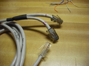
Now that you have one splitter, go ahead and do it again with the other Cat-5 patch cord. When you are complete, your patch cord should look like the following image.
Final Thoughts
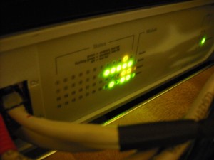
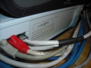
Now that you have a pair of these splitters, you should be able to enjoy a bit more freedom when setting up your network in a structured wiring environment where additional cable runs are simply not feasible. In my particular installation, I am using my splitters to feed the router’s output that carries VLAN tagged traffic into a managed switch. The other leg of the splitter, goes back to the wiring closet to feed a mini-switch with network connectivity. VLAN tagged traffic will not traverse a non-managed switch so for me this was the only way to be able to use my VLAN tagged network and my “primary” network without having to give up either. Below is an image of my splitter feeding my 24 port switch. Yes the switch is on however it appears that the flash washed the lights out.
I hope you enjoyed this quick post as I did making the splitters. Reply to this post and tell others how you intend to use your splitters.
Happy Hacking!
FIRESTORM_v1
10 Comments for this entry
1 Trackback or Pingback for this entry
-
Making structured wiring do your bidding - Hack a Day
July 30th, 2011 on 8:04 am[…] So you’ve just moved into a home that has cat5 running throughout. This is called structured wiring and is a great feature for a home. But what if the existing wiring doesn’t work the way you would prefer to setup your networ? [Firestorm_v1] has a workaround that lets you reconfigure Ethernet without pulling new cables. […]
July 30th, 2011 on 12:56 pm
As an IT professional (I think of myself as a professional hacker), I heartily agree. Too many IT guys would have a heart attack if they saw this, though.
Just to add, you could also run Ethernet and two phone lines down one cable. Also, true PoE can run over only two pairs. (Test this out before hand, though. Many PoE injectors don’t support it.)
When I set this up, I prefer to pull the plate off the wall, and replace it with a two port plate, and wire the jacks separately. It looks a bit nicer than a two headed cable.
Still, it’s a great tip.
~Jonathan
July 30th, 2011 on 6:51 pm
There are also pre-made, very cheap things that do this without having to get all the cable-making tools and materials, like this set of two:
http://www.play.com/PC/PCs/4-/3516468/Cat5-RJ45-Ethernet-Network-Splitter-Economiser-Adapters/Product.html
This kind of wiring is not really recommended, but will work perfectly fine if it is only used with 10/100 devices. Running Gigabit over only two of four pairs will not work properly, even if the devices report that the link is at Gigabit speeds.
July 31st, 2011 on 12:11 pm
Thank you both for taking the time to comment! You are correct, while not the “ideal” solution, it’s one that’s “good enough”.
Ironically, when I went to look for the adapters at Microcenter that HerpDeDerp spoke of, I didn’t find ones that had this functionality. I did find two-port RJ45 splitters, however they duplicated the pins 1 to 1 and didn’t split the signal wires into new pairs. Looking at the link that Herp provided, that looks like the adapter that I saw at Microcenter however without a close-up or a pin-schematic, While it might work for POTS phones I would not be able to tell for sure if it would work for CAT-5 Ethernet connections.
Additionally, I went looking for a dual insert biscuit jack like the ones I used for the Ethernet Tap (see http://www.yourwarrantyisvoid.com/2011/04/06/homeland-security-build-a-passive-ethernet-tap/) but they were sold out and wouldn’t have any in for a couple of weeks. Generally speaking, if you’re looking to make a set of splitters, I would suggest the use of a biscuit jack and two CAT-5 inserts instead of splitting out a patch cord.
If I get the parts, I’ll follow up with an update to this article demonstrating how to do the same thing with inserts instead.
July 31st, 2011 on 9:41 pm
I am very intruigued by this concept, as an electrician who is forced into doing home network stuff, often a service call environment (ie- no holes in the walls allowed) this could really come in handy. I am a bit confused on your wire number positions though. According to your instructions you are using pin 3,6,7,8 ; however if I’m reading the zytrax.com site correctly you need to use 1,2,3,6. Could you help me out with that?
Also someone mentioned pairing phone down the same cable, to you have any thoughts and/or reservations about this?
Thanks.
August 2nd, 2011 on 5:17 am
Hi Firestorm,
Have you got an email I can contact you on? I have a few questions to run past you.
Thanks
Ryan
August 3rd, 2011 on 4:55 am
Hello Al:
The only difference between my pin numbering convention and the ones on the zytrax.com site is the way the CAT-5 connector is held. When I was working telco, I was always trained to hold the spring clip to you and the wires to the left(white/brown on top). The zytrax.com site lists the clip to you wires to the right (white/orange on top). As long as you follow the wiring appropriate to the orientation of the clip, you shouldn’t run into any issues.
As far as sending phone down the same cable, you would be able to do so using either the white/blue pair or the white/brown pair. As long as you are consistent on both ends, you will be able to do so easily. Alternatively (and with a bit of soldering) you could build a custom Power over Ethernet jack and use this method to deliver power and network connectivity to a remote device that may not natively support it.
Hope this helps!
FIRESTORM_v1
October 10th, 2011 on 11:45 pm
Wow. This is freakin awesome! And I love the lighter as a tool. Stay classy San Diego 🙂
October 17th, 2011 on 8:07 pm
Well, Texas, actually, but thank you for the comments!
December 12th, 2011 on 2:15 pm
hi.is there any scientific reason for the color codeing? i thought maybe over long runs induction might have an influence and that the coding may decrease it or something. the reason i ask is because i did an 80 meter run with no specific code,just matched the ends. i tested the lead with proper test equipment and it was perfect. when i connected it up, the device(hmi) gave an error. however when i changed it to the colour code i worked fine. this made me very curious. any help or theorys.THANKS
December 19th, 2011 on 8:56 pm
Hello:
It would really depend on the device that you’re using. Cat5 and Cat6 spec does require a certain amount of twists per foot and a low twist count can impede performance. I don’t recommend this on really long runs due to the fact that we’re technically “cheating” the spec however in a pinch and for short runs, you’re not doing yourself any harm. Switches and ethernet cards have only improved in reliability and signal loss detection so that increase in reliability allows us to get away with things like this.
If I understand your post, you’re using an HDMI to Ethernet adapter? That being the case, it’s possible you had the standard mis-wired and this is what caused the device not to work. The ones I’ve seen use either 10/100 or Gigabit wiring which does expect certain signals to be present. Glad to hear that you got the devices up and running!
FIRESTORM_v1