Add an SD card slot to a WRT54G v2
by firestorm_v1 on Sep.09, 2009, under Embedded devices, Hardware, How-To's, Linux
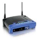 In this post, we’ll cover step-by-step how to add a SD cardslot to your Linksys WRT54G running DD-WRT and how to configure it in the DD-WRT UI. Granted, this has been done a lot already, however there is a significant lack of information on how to do it on the older V2’s. Read more for the complete step-by-step guide.
One of the advantages to using alternative firmware on “stock” devices is that it allows you to unlock the full potential of your hardware. Using the latest version of DD-WRT, you can now enable esternal storage on your WRT54G to add to the default image. With additional storage for your router, the possibilities are endless.
PLEASE NOTE: The pictures and information for adding the SD cardslot is only applicable to the Version 2 of the Linksys router. Attempting to do this on newer routers using this guide may result in damage to the router, the SD card or both. You can not hold me liable for any damage, so please read first and do some research before you crack the case open. The 15 minutes you may spend now may save you some blue smoke later.
Items Required:
- SD card slot – I stole one out of a 4 in one card reader from a failed hacking attempt from another project.
- SD card – Use a cheap one to verify it’s working first, then use whatever size you want.
- A piece of PCB – I used a piece of board that I had left over from another project, but this one from Radio Shack works well too.
- Jumper Wire – If you have multiple colors, this would be beneficial in keeping the lines straight for wiring.
- Small nuts and bolts
- Fine Tip soldering iron
- Dremel cutting tool
- (Optional) Razor Knife or X-acto Knife set
First thing’s first. This howto only covers the process of adding the card slot to the router and configuring DD-WRT. It does not cover installing DD-WRT on the router or which router is best for the process. The process of installing DD-WRT is very very well documented as well as the router’s specs for supported devices over at the DD-WRT Wiki.
Getting to know the SD card
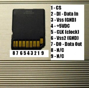 The SD card pinout shown above indicates that although the card has 9 pins, we will only be using 7 of them. Unlike most devices, the indented pin is not pin 1, but is pin 9, with pin 1 next to it. Here’s a quick reference showing what each pin is and what it does:
- Pin 1 – Chip Select – When this is brought high, the SD card is “turned on” and allows it to receive data or send data in sync with the CLK pin (pin 5)
- Pin 2 – Data In – This pin is used to receive data from the WRT54G for writing or for commands
- Pin 3 – Vss (GND) – This is a ground pin and is tied to Pin 6 for one less wire to deal with. It is important that both pins be brought together.
- Pin 4 – VCC (or +5VDC) – This pin supplies power to the SD card.
- Pin 5 – CLK – This is the clock line that the WRT sends to the SD card. This pin synchronizes the data coming in or going out of the WRT54G so that the SD card has the proper timing to read and write data.
- Pin 6 – Vss (GND) – This pin is also ground.
- Pin 7 – DO – This pin is data out to the WRT54G
- Pin 8 – Not Connected for this project.
- Pin 9 – Also not connected for this project.
We will be using some connections in the WRT54G called GPIOs to connect the various pins of the SD card to the WRT54G’s hardware. These GPIO pins are already used for other functions, but with the driver built into DD-WRT, we can use them to also control the SD card.
Step 1: Prepare the SD Card slot:
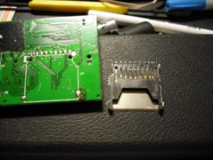 This is a picture of the SD card slot that I will be using.
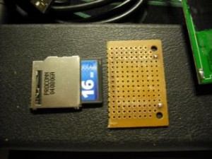 In this picture, I felt it necessary to scrape off the PCB solder pads under the SD card itself. This is where the X-acto knife kit comes in handy. The two solder “dots” in between the screw holes is for anchoring the tabs of the SD card slot and is recommended for making the card slot resistant to damage from repeated inserts and extracts.
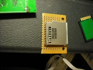 In this shot, I have lucked out. Each of the pins from the card slot match one of the solder pads on the PCB with no difficulty. This will greatly help soldering the wires to the cardslot.
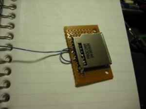 I recommend starting off with the ground wires, pin3 and pin 6. The little loop is the bridge between the two.
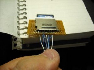 Wire the rest of the wires to their respective pins on the SD card slot. When all is said and done, you should have 6 wires. At this point, we’re done with the card slot and we’re ready to start soldering to the WRT54G.
Step 2: Making connections
If you haven’t done so already, go ahead and take the WRT54G apart.
- Start by unplugging the WRT54G’s power and network cables.
- Unscrew both of the antennas and set aside
- Grab the grey part of the WRT54G in one hand and the blue part in your other hand.
- Pull the two halves apart and set the blue part aside.
- Slide the top cover away from the bottom half of the WRT54G.
Now for the hard part. There are six locations that need to be wired up in order for this to work properly. We’ll start off with the easy one. Pin 1 (CS) goes to the + side of the DMZ LED. In this orientation, the component side of the PCB faces away from you, essentially you’re looking up from the bottom.
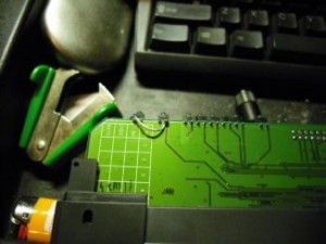 Attach the pin 1 lead to the right pin of the DMZ LED.
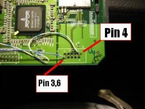 In this picture, we will be using the In Circuit Programmer port for pin 4 and pins 3,6. The Pin 4 (+5V) goes to the pin 1 on the ICP port, while the pins 3,6 (GND) goes to pin 10 of the ICP port. Orient the router so that the two antennas point up and away from you and that the component side faces you. The ICP port is an unpopulated 10 pin header located in the lower right hand quadrant of the router’s circuit board.
The next three leads are the most important AND the most difficult. You can click on the image to get a larger view if you need it.
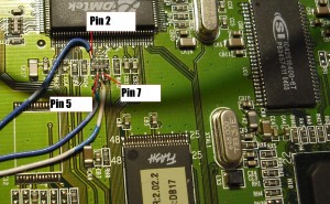 With the same orientation discussed as before, just south of the ADMtek chip is where the last three pins go. This is the hardest part of the build as you must attach to a resistor network that itself is very tiny. It took me several attempts and I had to superglue the wires down so that they wouldn’t move (not shown in this shot).
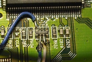 Here is an EXTREME close up of the resistor network (still same orientation). This is a 4 resistor chip, with 2 rows of 4 pins each. Pin 1 is the upper left hand corner and is wired to DI (pin 2) of the SD card. Pin 6 (second from the left on the lower side of the resistor network) goes to the CLK (pin 5) of the SD card, while pin 7 of the resistor network is wired to DO (pin 7) of the SD card.
Step 3: Box it up!
Now that you’ve gotten the card set up, it’s time to put it together. Now, there are many a howto that have a million and one locations to mount the card slot. I wanted something that didn’t look kludged together or didn’t have the cardslot sticking out of some random location. I instead chose the back of the WRT, just above the ethernet ports.
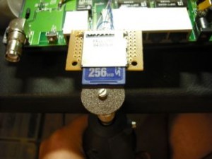 Thankfully for me, the SD card was slightly larger than the diameter of the cutting wheel of my Dremel. Making a single cut was quite easy.
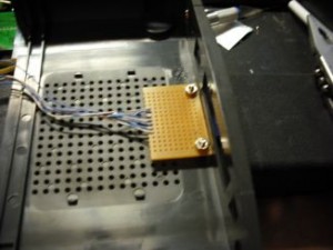 I made my cut just above the Ethernet ports and secured the PCB to the top cover. The bolts holding the PCB in place were just short enough to clear the RJ45 connection block so no additional work was necessary.
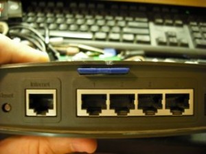 Here’s a view after the WRT54G completely assembled (and also where my Dremel nicked the plastic cover)
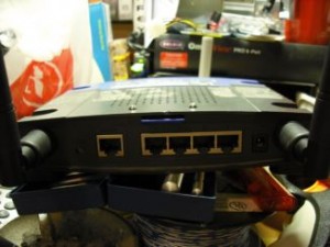 One more shot of the completed mod, the only thing I would like to have done is found countersunk bolts. Unfortunately, I was limited to what I had on hand at the time. All in all, it’s a very clean modification.
Step 4: Configure DD-WRT
Now all that’s left to do is to configure DD-WRT. Before we begin, make sure that you have cleared out the SD card of any data you want prior to working with it. Once we get the card working, the router will format the card with an EXT3 filesystem, erasing anything already on the card.
Go ahead and hook up the router to power and network. Don’t stick the SD card in just yet, first we have to configure DD-WRT for the card. Click on “Managment” and scroll down to the “MMC/SD card support”. Enable it if it’s not already enabled and set the GPIO pins detect to “Manual”.
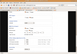 When you select “Manual”, you will need to put in some numbers for the four signal leads. I used the following settings:
- DI (Data In) – GPIO 5
- DO (Data Out) – GPIO 3
- CLK (Clock) – GPIO 4
- CS (Chip Select) – GPIO 7
Scroll down, and hit “Save Settings”. The screen will fade out then fade back in. Once the screen fades back in, disconnect the power from the WRT and insert your SD card. Power on the router and you should notice that the DMZ LED starts flashing intermittently. This is good news.
Log back into the DD-WRT admin panel and hopefully, if everything is correct, you will see values filled in for Total/Free Size. If you do, then congratulations. you’re done! You can login via Telnet to the router and see that it’s mounted and ready to roll.
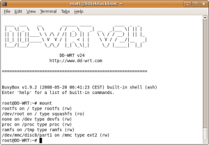 From here, you can now compile things on a Linux box, save them to your SD card and then use your SD card to launch your programs on the WRT itself. Just remember to mount and umount the card and you won’t have to worry about corrupting the filesystem on the card.
Afterword:
Thanks goes out to the DD-WRT user community for making this possible and thanks goes to the original person that hacked out GPIO SD-card support into the kernel running on DD-WRT.
July 28th, 2010 on 2:54 am
THANKS for putting this up, I just ran out of storage, man I hear that some of these have 32mb of ram and only 16 is enabled by default requiring a softmod to enable the other 16m, but I see 32mb in the www interface, so not sure how true that is.
Please keep this up as I plan to do this very soon as I get the parts, thanks!
March 22nd, 2011 on 5:25 am
Hey I liked the tut. however i think im having trouble with GPIO5 do you know how to test this?
I can read the card but not write.
March 22nd, 2011 on 6:09 am
I have found gpio 5 for my board rev:XH just underneath where this tutorial said.
i tested it with
while true;do gpio enable 5;sleep 1;gpio disable 5;sleep 1; done
then tested the pins with a multimeter
So now i know they are all where i expect them to be.
however i still cant create anyfiles in the /mmc dir 🙁
March 22nd, 2011 on 11:04 am
Hello Phillip:
That’s a great solution to finding the GPIO pins, I think I had to do that once or twice when I wrote the article. I didn’t think to put it in there, but kudos on figuring out the fix!
You might need to give it a few minutes, depending on the size of your SD card and whether or not the card was formatted ext3 when you put it in. One thing I noticed was that the card was instantly reformatted upon insertion as it was originally formatted FAT32. And, I’m sure you’ve checked it but check once more and make sure that the Write Protect switch is unset. (I had this happen to me too on an unrelated project, set me back for a day. 😛 )
If you are still unable to write, use your oneliner script to check your other GPIO pins per the article. Unfortunately, I’ve sold my unit since the article was written so I’m not sure I can assist much further than the information in the article. I’ll try to help as much as possible, but can’t guarantee anything.
Good Luck!
FIRESTORM_v1
October 10th, 2011 on 12:31 pm
Hi friend ! This mod also works on v2.2!
Thank’s!
October 17th, 2011 on 8:07 pm
Excellent! Thank you for letting me know. I’m sure it will be useful when I look for replacements.
January 26th, 2013 on 12:21 am
Which is the porpuse for adding a SD card? it can be used as network data storing? streaming? please advice.. I have an old router 🙂 I want to test, but I need to know the final usage.
February 28th, 2013 on 4:06 pm
Hello Fernando:
The use of adding an SD card was that if you needed to do any packet logging or packet sniffing, wanted to capture log messages or wanted to roll your own packages, you could copy the files to/from the SD card without worrying about running out of flash storage in the router itself. Most routers don’t have very much space to add additional packages so the SD card would give you more space to install extra stuff.
FIRESTORM_v1
July 9th, 2013 on 7:29 pm
I have one with this mod that I made several years ago. Unfortunately it’s been stored away for about 2 years, and I have forgotten if I changed anything or upgraded the firmware. It used to run like a top.
Getting it back out and resetting it, I see it still shows the MMC option in the Admin tab, it allows that to be selected and will report the MMC usage but when I check kernel support for it, there’s no /dev/discs/* to be found.
Like I said I may have updated the firmware and that’s the reason I stashed it. (24-sp2 is on it now) So BEWARE! If you upgrade or change versions, your support for this may break completely!
July 13th, 2013 on 6:08 am
Does anyone know if this works on the WRT54GS model?
Thanks.
July 18th, 2013 on 1:18 pm
Good question. I’m not entirely sure. I haven’t used this WAP in a couple of years now, having moved on to pfSense for my router and using a Cisco WAP. Provided that the WRT54GS has the same requirements (GPIO pins and can run DD-WRT), you should be good to go, but I haven’t a clue where to connect anything up.
Good Luck!
FIRESTORM_v1